


22 www.pridemobility.com Victory Sport
III. YOUR SCOOTER
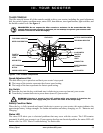
Batteries
The batteries store electrical energy that powers your scooter. See IV. “Batteries and Charging” for
information on how to charge your scooter batteries.
Anti-Tip Wheels
The anti-tip wheels are an integral and important safety feature of your scooter. They are bolted to the
frame at the rear of the scooter.
PROHIBITED! Do not remove the anti-tip wheels or modify your scooter in any way that
is not authorized by Pride.
WARNING! The anti-tip wheels may cause interference with the smooth transition of your
Travel Scooter when ascending or descending a curb. Contact your authorized Pride
Dealer for more information.
Motor/Transaxle Assembly
The motor/transaxle assembly is an electromechanical unit that converts electrical energy from your
scooter’s batteries into the controlled mechanical energy that drives the scooter’s wheels.
Manual Freewheel Lever
Whenever you need or want to push your scooter for short distances, you can put it in freewheel mode.
1. Remove the key from the key switch.
2. Push forward on the manual freewheel lever to disable the drive system and the brake system. This will
enable you to push the scooter.
3. Pull back on the manual freewheel lever to reengage the drive and the brake systems and take your
scooter out of freewheel mode.
WARNING! When your scooter is in freewheel mode, the braking system is disengaged.
Disengage the drive motors only on a level surface.
Ensure the key is removed from the key switch.
Stand to the side of the scooter to engage or disengage freewheel mode. Never sit on
a scooter to do this.
After you have finished pushing your scooter, always return it to the drive mode to
lock the brakes.
NOTE: If the scooter is placed in freewheel mode (manual freewheel lever forward) while the key is in
the “on” position, the scooter will not run until the manual freewheel lever is pushed backward and the
key is turned to the “off” position, then back to the “on” position.
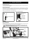
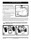
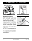
Safety Flag Bracket
An accessory bracket for installing an optional safety flag is mounted near each anti-tip wheel. See
figure 7. To install the flag, the supplied L-shaped hex key is needed.
To install the safety flag:
1. Remove the cap from the top of the bracket.
2. Loosen the setscrew with the supplied L-shaped hex key.
3. Insert the flag pole into the opening.
4. Tighten the setscrew to complete installation.