


Basic Operation Instructions 9
www.pridemobility.com Microdrive Controller
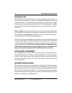
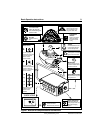
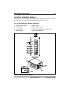
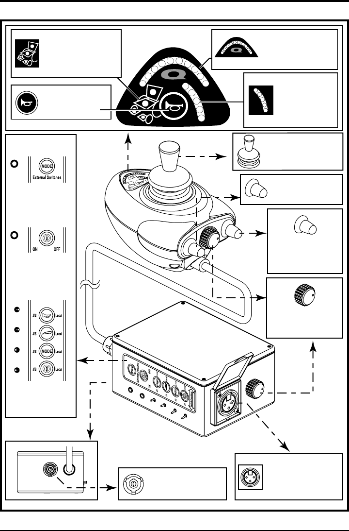
Figure 1. Microdrive Components and Connections
BACK VIEW
Harness Connector Port
Used to connect the
Microdrive to the power base.
Joystick
A multi-functional tool used
to control speed, direction,
and actuator adjustment.
On/Off Switch
Press to power on or off the
power chair and controller.
Mode Switch
Used to select the various
functions available with the
Microdrive Controller.
Speed Adjustment Dial
Adjusts the maximum speed
of the power chair.
Horn Key
Activates a warning
horn.
Actuator Indicators
Four LEDs indicate
recline, tilt, power leg
rests, and elevating seat
actuator modes.
Battery Condition Meter
Indicates the approximate
amount of battery charge
using color-coded LEDs.
Profile/Speed
Indicator
Series of five colored
LEDs which display
the speed or profile
setting.
Battery Charger Port
Standard 3-pin XLR type
battery charger socket used
with off-board charging
systems.
Toggle switches to allow
or disallow various
functions via the
controller.
Joystick Interface
Module Controls
A 3.5 mm (1/8") jack
socket to allow connection
of external switches to
select the various
functions available
A 3.5 mm (1/8") jack
socket to allow connection
of external switches to
power on or off the power
chair and controller.