


Quantum Jazzy 1420 Series www.pridemobility.com 23
COMFORT ADJUSTMENTS
After becoming familiar with your power chair’s operation, you may find the need to make some adjustments to
increase your comfort, such as seat height and angle, armrest angle, foot platform height and angle, and controller
position.
NOTE: If your power chair is equipped with a Synergy Seat or TRU-Balance Power Positioning System, refer
to the information provided in separate manuals. If your power chair is equipped with a medium-back, a high-
back, or a reclining seat, refer to the following information.
WARNING! The center of gravity of your power chair was factory set to a position that meets the
needs of the demographic majority of users. Your authorized Quantum Rehab Provider has
evaluated your power chair and made any necessary adjustments to suit your specific
requirements. Do not change your seating configuration without first contacting Pride Mobility
Products or your authorized Quantum Rehab Provider.
WARNING! Some power chair components are heavy. You may need assistance to lift or carry
them. Please refer to the specifications table for specific component weights before you
disassemble the power chair.
WARNING! Remove the occupant from the power chair before making any adjustments.
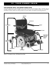
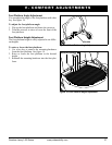
V. COMFORT ADJUSTMENTS
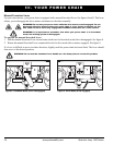
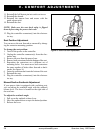
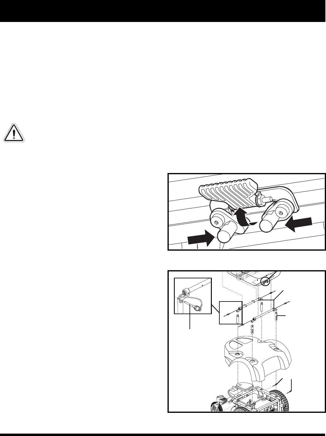
Figure 14. Seat Latch Safety (Disengaged)
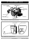
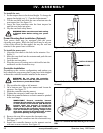
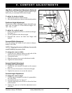
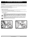
Figure 15. Seat Height Adjustment
QUICK-RELEASE PIN
TRAPEZE BARS
SEAT TOWER
You may need the following to make comfort
adjustments:
metric/standard hex key set
metric/standard socket set and ratchet
adjustable wrench
Seat Height and Angle Adjustment
The seat is attached to the power base through the
UMS. You can change the seat height by raising the
front and rear seat towers. If you raise or lower only
one set of towers (front or rear), you can also change
the seat base angle (dump).
To change the seat height:
1. Turn off the power to the controller.
2. Unplug the controller connector(s) from the elec-
tronics tray.
3. Flip up the seat latch safety. See figure 14.
4. Squeeze the seat latch and release the seat from the
front trapeze bar.
5. Slide the seat forward and remove it from the
power base.
6. Remove the quick-release pins from the seat tow-
ers (front and rear). See figure 15.
7. Remove both trapeze bars from the seat towers.
8. Lift off the shroud.
9. Remove the ball detent pin from each of the four
seat towers. See figure 15.
10. Move the seat towers up or down to the desired
height.
BALL DETENT PIN