


C3419M-B (11/06) 3
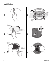
1. Locate the center point of the mounting location and insert the compass tool. Draw a circle.
2. Cut the circle out of the ceiling.
3. Use the mounting ring as a template and mark the screw hole pattern onto the mounting surface. Prepare the holes.
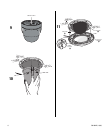
4. Install the mounting plates. Use the eight 10-32 x 3-inch screws (supplied) and install the mounting ring (A) and two
back mounting plates (B).
a. Line up the mounting ring with the eight fastener holes.
b. Feed one back mounting plate (B) through the hole in the ceiling (C) and line up with four fastener holes.
c. Install fasteners through the mounting ring (A), ceiling, and out the back mounting plate (B).
d. Install second back mounting plate (B).
5. Attach the conduit fitting, lock nut, and safety chain bracket. Install a safety chain/cable (not supplied) that will
support up to 16 pounds (7.3 kg).
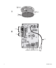
6. Open the hinged door to the back box. Push the tab lock towards the wall of the unit and lift the door open.
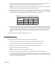
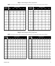
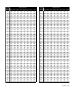
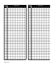
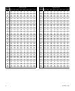
Pull wiring into the back box through the conduit fitting. Refer to Table A, Table B, and Table C for wiring distances.
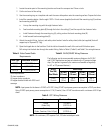
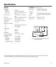
NOTE: Input power for the dome is 24 VAC or 24 VDC. Using 24 VAC input power, power consumption is 23 VA per dome.
Using 24 VDC input power, power consumption is 0.7 A (15 watts). Use a 24 VAC transformer with a minimum of 40 VA per
dome.
.
NOTE: As a minimum, UTP requires Cat5, 100-ohm twisted pair cable.
Table C. UTP Wiring Distances
Receiver Maximum Distance
Active
(Video Only)
0-3,000 ft
(0-914.4 m)
Passive
(Video, Coaxitron, Pelco V-Sync)
0-750 ft
(0-228.6 m)
*Cable requirements:
75 ohms impedance
All-copper center conductor
All-copper braided shield with 95% braid
coverage
Table A. Video Coaxial Cable
Requirements
Cable Type* Maximum Distance
RG59/U 750 ft (229 m)
RG6/U 1,000 ft (305 m)
RG11/U 1,500 ft (457 m)
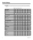
Table B. 24 VAC/24VDC Wiring Distances
The following are the recommended maximum distances for 24 VAC
and 24 VDC applications and are calculated with a 10 percent voltage
drop. (Ten percent is generally the maximum allowable voltage drop
for AC- or DC-powered devices.)
AC/DC
Total VA/
Total Watts
Wire Gauge
20 AWG
(0.5 mm
2
)
18 AWG
(1.0 mm
2
)
16 AWG
(1.5 mm
2
)
14 AWG
(2.5 mm
2
)
23 VA/
15 watts
123 ft
(38 m)
196 ft
(60 m)
311 ft
(95 m)
495 ft
(151 m)