


INSTALLATION PENDANT MODELS
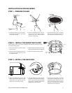
STEP 1 - MOUNT AND INSTALL THE BACK BOX
NOTE: If installing outdoors make sure the installation is properly sealed to keep moisture out.
00540
00535
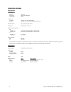
a. Install the mount for the pendant dome. Refer to the instruc-
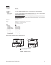
b. Turn the thumbscrew and open the hinged door located inside
tions supplied with the mount. Bring the wiring for the dome
the back box.
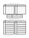
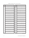
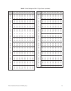
through the mount. Refer to Tables A and B in the Appendix for
wiring distances.
00541
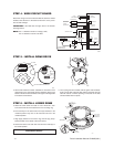
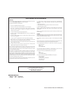
c. Pull wiring from the mount into the back box.
d. Screw the back box into the mount. If outdoors, apply thread
compound (provided) to the threads on the back box.
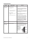
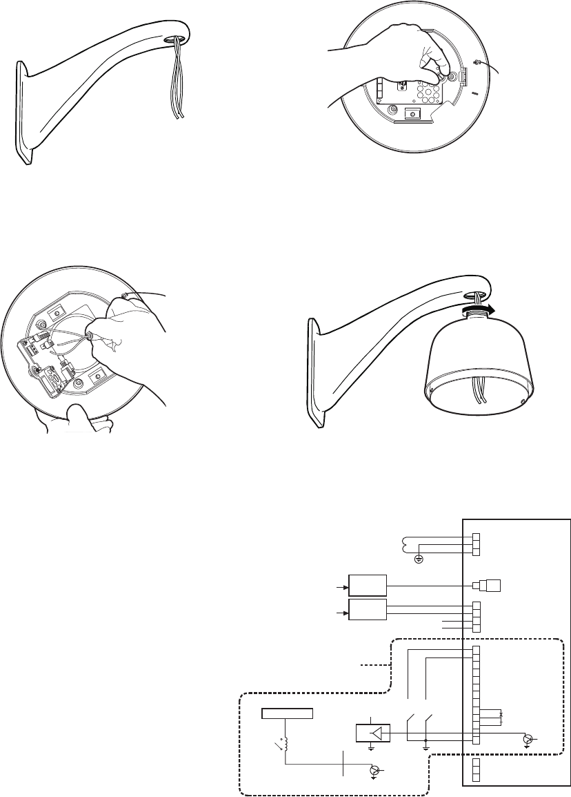
STEP 2 - WIRE CIRCUIT BOARD
Attach the wiring to the interconnect circuit board inside the back
box. Close the door to the back box. Turn on power to the back
box. The red LED will light.
IMPORTANT: If the LED does not light, refer to the
Trouble-
shooting section
.
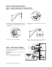
NOTE: Aux 1 - Maximum 2A at low voltage (<40V)
Aux 2 - Maximum 150 vA at 32 VDC
+5 to +24 VDC
NOT USED
NOT USED
TX-
TX+
VIDEO IN
CONTROLLER
TX-
TX+
RX-
RX+
SWITCHES
(WIRING EXAMPLE)
1
2
3
4
5
6
7
ALARM
INPUTS
GROUND
+5 VDC
AUX 2
HEATER/FAN (NOT USED)
VIDEO OUT
GROUND
AUX 2
(NO)
(NC)
RELAY
(AUX 1)
CONTROL
(RS-422)
LOGIC GATE
(WIRING EXAMPLE)
EXTERNAL RELAY
(WIRING EXAMPLE)
24 VAC
TRANFORMER
COAXITRON
CONTROLLER
2 WIRE
CONTROLLER
POWER
(24 VAC ONLY)
SPECTRA II ONLY
00542
Pelco Installation Manual C2429M (3/01) 7