


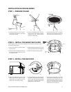

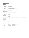
STEP 4 - WIRE CIRCUIT BOARD
Attach the wiring to the circuit board inside the back box. When
finished, close the door to the back box and turn on the power.
The red LED will light.
IMPORTANT: If the LED does not light, refer to the
Trouble-
shooting section
.
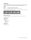
NOTE: Aux 1 - Maximum 2A at low voltage (<40V)
Aux 2 - Maximum 150 vA at 32 VDC
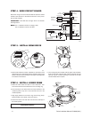
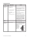
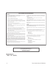
STEP 5 - INSTALL DOME DRIVE
LABEL
SW1
L
A
B
E
L
S
W
2
SW1
SW2
RS-422 TERMINATION SWITCH
ON
1
2
3
4
5
6
7 8
ON
1
2
3
4
5 6
7
8
SW2
00538
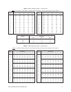
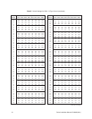
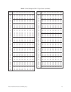
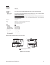
a. Set the DIP switches for SW1 and SW2 on the bottom of the
dome drive for the appropriate receiver address. Refer to the
labels on the dome drive or Tables C through E in the Appendix
in the back of this manual.
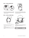
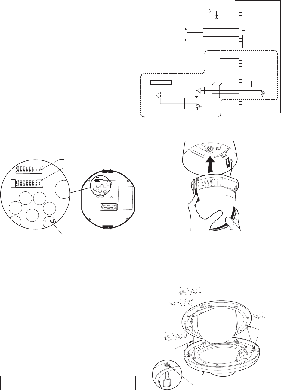
STEP 6 - INSTALL LOWER DOME
a. Attach the lower dome trim leash to one of the 8-32 x .275-
inch screws that secure the back box to the mounting ring.
b. Insert both keys in the barrel locks. Turn keys clockwise to the
unlocked position. Keys can not be removed from lock in the
unlocked position.
c. Align pegs (located on the mount ring) with the peg recep-
tacles (located on the inside of the lower dome).
d. Place lower dome over back box. Hold and turn both keys to
the locked position.
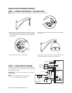
+5 to +24 VDC
NOT USED
NOT USED
TX-
TX+
VIDEO IN
CONTROLLER
TX-
TX+
RX-
RX+
SWITCHES
(WIRING EXAMPLE)
1
2
3
4
5
6
7
ALARM
INPUTS
GROUND
+5 VDC
AUX 2
HEATER/FAN (NOT USED)
VIDEO OUT
GROUND
AUX 2
(NO)
(NC)
RELAY
(AUX 1)
CONTROL
(RS-422)
LOGIC GATE
(WIRING EXAMPLE)
EXTERNAL RELAY
24 VAC
TRANFORMER
COAXITRON
CONTROLLER
2 WIRE
CONTROLLER
POWER
(24 VAC ONLY)
SPECTRA II ONLY
(WIRING EXAMPLE)
GREEN
TAB
RED
TAB
00539
b. Line up the green and red tabs with the green and red labels.
Push in on the tabs. Insert the side with the green tab, then the
side with red tab. Continue pushing on the ends of the tabs
until both sides click into place.
BARREL
KEY LOCK
BALL STUD
RECEIVER
BALL STUD
00497
TRIM LEASH
TO USE YOUR DOME, REFER TO THE OPERATION AND
PROGRAMMING MANUAL.
Pelco Installation Manual C2429M (3/01) 6
00542