


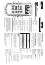

Top Side:
1. RS232 (Optical Interfaced) Port
2. Sockets of thermocouples T1
3. Sockets of thermocouples T2
OPERATING INSTRUCTIONS
Operational Mode
There are three operation modes–Normal, Shift, and
Setup Mode.
Normal Mode:
This is the default mode; the operating functions for the
normal mode are printed on the top of each button in white.
Shift Mode:
The operating functions for the shift mode are printed in
yellow on the buttons. While in the normal mode, push
the SHIFT button to switch to shift mode. At the lower-
righthand corner of the display panel, the word “Shift” is
displayed to indicate shift mode. To switch back to normal
mode, press the SHIFT button.
Setup Mode:
The operating functions for the setup mode are printed
in between two bracket signs “[ ]“ on each button. Press
the SET[ ] button in normal mode to switch to setup mode,
the indicator “SET” is shown on the left side of the display
panel. To switch back to normal mode, press the SET[ ]
button.
Normal Mode:
The following functions can only be used in the normal
mode.
(1)
“
I
Power Button
The“
I
” button turns the thermometer on or off. When
entering data set mode, the power off function is disabled.
(2) “Limits” Button (only main display)
The limits function will alert the user when a measure-
ment exceeds a specified limit. To set the limit values, refer
to limits function in the setup mode.
Press the [Limits] button to activate the limits function; the
word “LIMIT” should be displayed on the LCD.
When the value of the main display exceeds the Hi limit, the
word “Hi” will be displayed and the thermometer will beep
in an interval frequency. If the value of the main display is
lower then the Lo limit, the word “Lo” will be displayed
and the thermometer will beep in a continuous frequency.
In Limits function, on K or J Type, and with the scale of
temperature at °F, the reading counts should be times 10.
(ex: 2100°F means 21000 counts)
To exit the Limits function, press the [Limits] button.
(3) “ ” button
The backlight function is represented by this button “
Pressing the button will turn the backlight on or off in the
”.
LCD.
(4) “SAVE/READ” button
The Read Data function works in conjunction with the
Save function in the Shift mode, it is used for reading saved
data. The Save function can be activated in Shift mode.
Press the SAVE/READ button to activate the Read Data
function; the word “READ” should be displayed on the
LCD. To navigate around the Saved Data table, press the
overlay “SECOND” button until the “#” sign is displayed on
the second display panel. The location of the read pointer
within the Saved Data table will be displayed. The arrow
buttons on the overlay are used for scrolling through the saved
data. Pressing the smaller arrow “
” or “ ” retrieves the
next saved data. Pressing the larger arrow “ ” or “ ”
will retrieve the next ten saved data. Pressing the overlay
“ESC” button deactivates the read data function.
(5) “LOG/READ” button
The Log/Read function works in conjunction with the log
function, it is used for reading the log data. The log function
can be activated in the shift mode. Press the LOG/READ
button to activate the read log function; the word “READ”
should be displayed on the LCD. Press the overlay SEC-
OND button to rotate through following display menus:
T1, T2, GRP, and #.
T1 and T2: Displays the T1 or T2 saved value.
GRP: Displays the current group number.
#: Displays the current location of the read pointer within
a selected group. The arrow buttons on the overlay are used
for scrolling through the data and groups. Press the smaller
arrows “
”or “ ” to retrieve the next log data or
group. Press the larger arrows “ ” or “ ” to retrieve
the next ten log data or groups. To navigate around the log
data and groups, press the overlay SECOND button till
GRP appears in the second display panel, and then select
the group using the arrows, then press the SECOND button
again till the “#” sign is displayed. The location of the read
pointer in the selected group will be displayed, and then use
the arrows to scroll through the data. Pressing the overlay
“ESC” button deactivates the read data function.
(7) HOLD mode (only main display)
When HOLD mode is selected, the thermometer holds
the present readings and stops all further measurements. To
activate the data hold mode, press the HOLD button, and
“HOLD” is displayed on the LCD. Pressing the HOLD
button again cancels the function, and the instrument will
automatically resume measurements.
(8) MIN/MAX with time record mode (only main
display)
The MIN/MAX function records the highest and lowest
value recorded, and it calculates the average reading, and
recorded. Press the MIN/MAX button again to rotate
the differences of MAX to MIN. Press MIN/MAX button
to enter the MIN/MAX recording mode. The beeper emits
a tone when a new minimum or maximum measurement is
through the current readings:
MAX: The highest measurement recorded.
MIN: The lowest measurement recorded.
MAX-MIN: The difference of the highest and the lowest
measurement.
AVG: The average values of the measurements. This mode
works in conjunction with the hold function, pressing the
HOLD button will stop the recording and measurements
(Previously recorded readings are not erased). Press HOLD
button again to resume recording and measurements. To
prevent accidental loss of MIN, MAX and AVG data, the
MIN/MAX function can only be cancelled by pressing and
holding down the MIN MAX key for more than 2 seconds.
The Automatic Power Off function, and the power, C/F,
REL, SET, Hi/Lo Limits, TYPE, T1/T2 buttons are also
disabled.
(10) “T1/T2” button (MAIN display)
The input selection button [T1/T2] selects the input
for the main display panel, T1 thermocouple or T2
thermocouple. Press the T1/T2 button to switch between
the two inputs. When meter is turned on, it is set to the
display that was last in use.
(11) “T1/T2” button (SECOND
display)
The input selection button [T1/T2] selects the input for
the second display panel, T1 thermocouple or T2 thermo-
couple. Press the T1/T2 button to switch between the two
inputs. When meter is turned on, it is set to the display that
was last in use.
(12) “T1-T2/TIME” button (THIRD display)
The input selection button [T1/T2] selects the system
time and date, or the differential between the two thermo-
couples (T1-T2) for the third display panel. Press the T1/
T2 button to switch the display options. When meter is
turned on, it is set to the display that was last in use.
SHIFT MODE
The following functions can only be used in the shift mode.
(2) “C/F” button
Press the C/F button to select the temperature scale,
readings can be displayed in Celsius (C) or Fahrenheit
(F). When the thermometer is turned on, it is set to the
temperature scale that was last in use.
(4) “SAVE” button
The save function stores the T1, T2 data in nonvolatile
memory. Press the SAVE button to save the current data.
The word SAVE is displayed to indicate the data are saved.
The build in memory can store up to 128 data. The data can
be read using the read function in the normal mode.
(5) “LOG” button
The data log function continuously records the data
according to a specified time interval. The time interval can
be set using the interval time setup function [INVT] in the
setup mode. Press the LOG button to activate the log
function; the indicator “LOG” and “MEM” will be dis-
played on the LCD. There are 16 groups that are used for
storing the log data, and each group uses 64 data slots. If
the current log session exceeds 64 data, the log function
will automatically use the next group to store the following
data. A maximum of 1024 data can be saved in one log
session. Press the LOG button again to exit the data log
function.
(6) “CLR ?” button
The CLR function clears all the saved and logged data in
memory. When the CLR button is pressed, indicator
“MEM” is displayed and the “CLR” word on upper-right
of LCD will blink. Pressing “ENTER” button printed on
the overlay in white word to clear all saved and logged data
or “ESC” button to exit this function.
(7) “REL” button (only main display)
The relative value function can be used for comparing the
saved reference value with other measurements. Press the
“REL” button to store the current measurement as the
reference value, and the “REL” should be displayed on the
right part of the LCD. The next measurement will display
the relative value compared to the reference value.
Press “REL” button again to clear the reference value and
deactivate the relative value measurement function.
(8) “[APO]” button
Press the [APO] button to trigger “Auto power off“
function on or off. In this function, the indicator “APO” is
shown at the upper lefthand panel of the LCD. When APO
(Auto power off) is enabled, it will automatically turn the
thermometer off if the key switch is inactivated according to
to the set time (the default time for APO is 5 minutes).
Press the Power button to resume operation.
”