


20
c. Remove the bottom case of the indicator.
d. Adjust the voltage calibrator for an output of
0.000mV and connect the minus lead from the
calibrator to “GND” and the positive lead
from the calibrator to “;+IN”, on the indicator
printed circuit board.
e. Disable the reference junction by jumpering
together the “REF J” and “GND” testpoints,
using a jumper lead terminated in mini-clips.
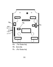
f. Adjust Rb for an indicator display of 0.0°C.
g. Connect the DVM LO lead to “GND”, on the
indicator printed circuit board.
h. Using HI lead of DVM, measure voltage
at the “-1.23V” testpoint: disregarding
polarity indication, record the voltage.
i. Move the DVM HI lead to the “3.7V”
testpoint and record the voltage (disregard