


19
Calibration Instructions 4
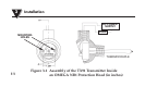
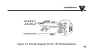
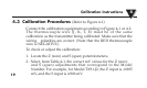
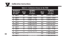
4.3 Calibration Procedures (Refer to Figure 4-1)
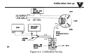
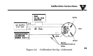
Connect the calibration equipment according to Figure 4-1 or 4-2.
The thermocouple wire (J, K, T, E) must be of the same
calibration as the transmitter being calibrated. Make sure that the
wiring polarities are correct. (Note that the RED thermocouple
wire is NEGATIVE.)
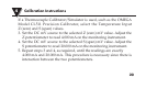
To check or adjust the calibration:
1. Locate the Z (zero) and S (span) potentiometers.
2. Select, from Table 4-1, the correct mV values for the Z (zero)
and S (span) adjustments that correspond to the Model
Number. For example, for Model TX91-J2, the Z input is -0.885
mV, and the S input is 4.906 mV.