


Page of 13
12
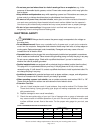
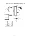
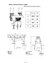
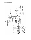
Part
#
Description
Part
#
Description
1 Support structure 27 52 × 25 × 15 bearing
2 Fixing ring 28 6 × 6 × 20 key
3 52 × 25 × 15 bearing 29 Rotor
4 Rope roll shaft 30 47 × 20 x 14 bearing
5 6 x 6 × 22 key 31 Nut (diameter 12mm)
6 Rope roll 32 Compression spring of brake disk
7 Protective sheath of rope 33 Spring of fan
8 Fixing clamps of support 34 Rectifier
9 Diameter of anti-rotating rope 6mm 35 Terminal box cover
10 Tensioning block of rope 36 Terminal box
11 Hook 37 Protective cover of motor
12 Front cover of reducer 38 Fan
13 Piston ring (47mm) 39 Slide handle
14 47 × 20 × 14 bearing 40 35Mf capacitor
15 Z-43 gear 41 Self tapping screw of protective cover
16 35 × 15 × 11 bearing 42 Brake disk
17 Z-10 gear 43 Brake coil
18 35 × 15 × 11 bearing 44 Emergency stop switch
19 Z-62 gear 45 Rise and fall switch
20 Pad 46 Control handle
21 Rear cover of reducer 47 Cable strain relief
22 Stud 48 6 × 6 × 16 key
23 Barrel of motor 49 Operation rod of limit switch (button box)
24 Casing of motor 50 Return spring of operation rod of limit switch
25 8 × 35 inner hexagonal bolt 51 Mini-switch box
26 12 × 36 washer 52 Mini-switch of single-phase limit switch
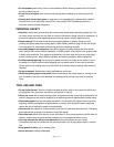
For replacement parts and technical questions, please call 1-800-222-5381.