v8.06 - Depósito legal y Copyright 2008. Todos los derechos reservados.
VMB ESPAÑOLA, S.A.
5. MAINTENANCE.
5.1 - Periodically check the condition of the
cable. If a cable is torn or broken it should be
replaced immediately. Do not use the lift if the
cable is not perfect. Only use torsion resistant
steel cable DIN 3060.
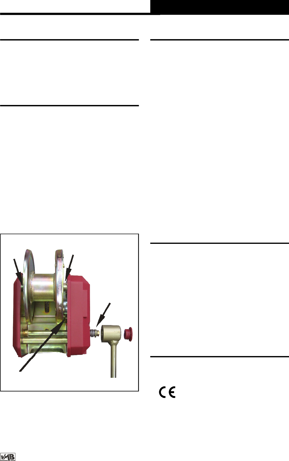
5.2 - The lift is supplied completely greased
from the factory. Never the less, we
recommend you periodically grease (depending
on amount used) the teeth of the winch (CD),
end point of the handle (RM), bar (EB) (Fig. 8)
and the profile nylon drums.
ATTENTION: Do not grease or lubricate the
break mechanism.
The brake discs have been greased with a
special heat and pressure resistant grease. Do
not use other products.
Quick Operation Guide
ENGLISH
7. CERTIFICATIONS
-
EC Machinery Directive
89/392/ECC and 98/37/ECC
- BGV C1 (GUV-VC1) / BGG 912 (GUV-G912)
6. GUARANTEE.
The warranty period for this lift is 3 years from
the date of purchase.
VMB Española, S. A. promises, that from from
the date of purchase and during the warranty
period to resolve any faults that may occur
produced through defect material or fabrication.
Damage caused by inproper use, product
modification, terciary manipulation or acciden-
tal fire are not covered by this warranty.
5.3 - All lifts should undergo an annual
technical inspection carried out by an
authorized VMB dealer to check the
certifications and general condition of all the
lift’s elements and security systems involved
in the lift’s use.
5.4 – Only use original spare parts to guarantee
a continued security level.
The user loses all rights to warranty if any spare
parts other than originals are used or carries
out any modification or alteration to the towerlift.
5.5 – To request a spare part please indicate
the corresponding code which can be found in
this manual.
VMB Tecnical Assistance
S.A.T. in Spain
Tel : +34 902 34 10 34
Fax: +34 961 22 11 77
Place the bars in their transport compartment.
Remove the outriggers, releasing the locks and
place in their transport position (S). Turn and
tighten the fixing screws (J). The lift can be
transported horizontally by adding the RH-4 kit.
EB
EB
CD
RM
Figura 8


