MODEL 314 DATALOGGING HUMIDITY TEMPERATURE METER
4
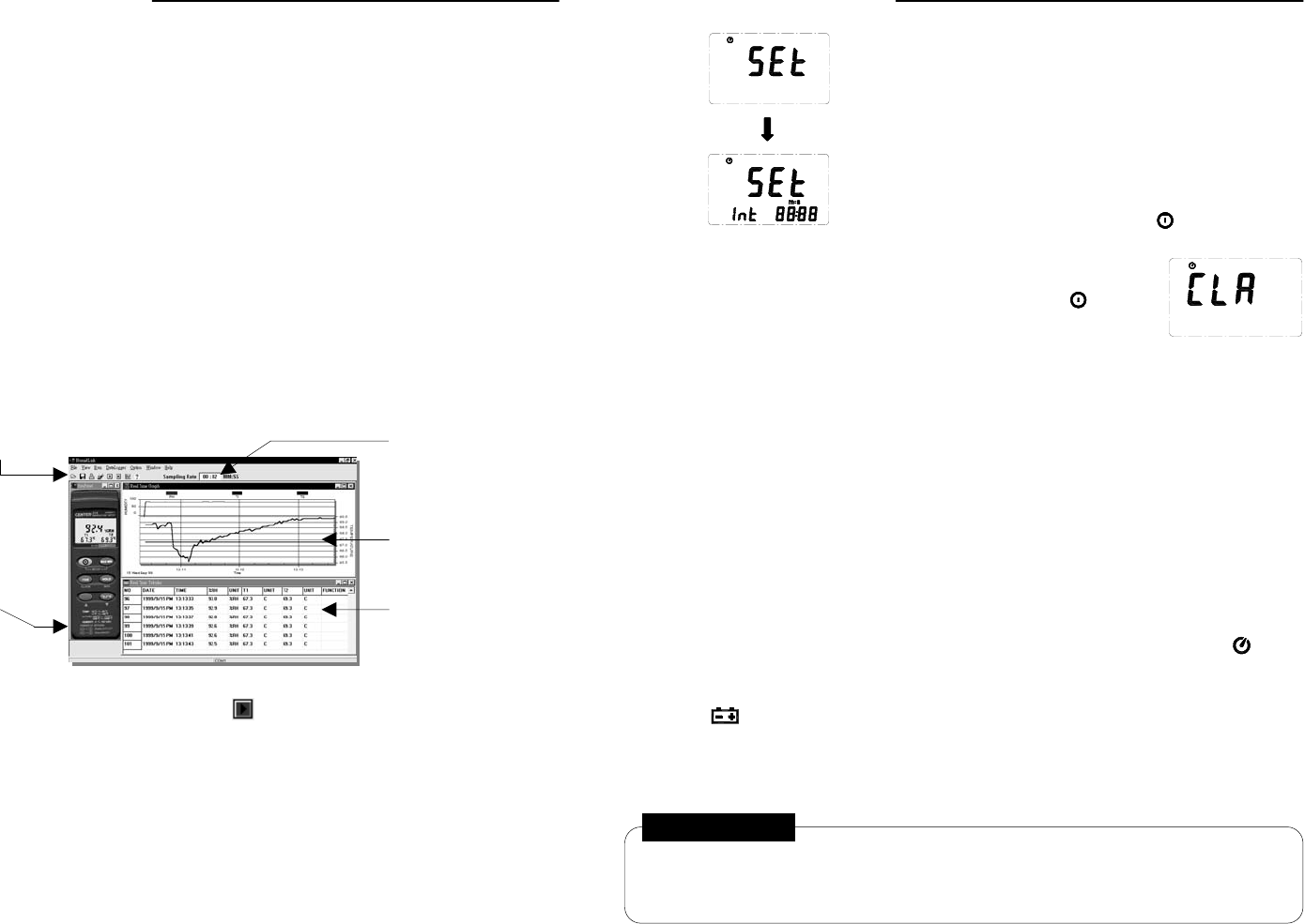
4.8 Recording Interval Setup
To set the recording interval:
1. Press and hold the MAX MIN button and then power on
the meter.
2. Press HOLD (interval).
3. Press REC (n) or °C/°F (p) to increase or decrease the number.
4. Press HOLD to advance to the next item.
5. Press HOLD again after the last setting to complete the process.
To abort during a setup process, press the button.
4.8 Recording Data
Each momentary press of the REC button will alternately start
and stop recording. To clear the memory, power off the meter,
press and hold the REC button followed by the button,
holding both on simultaneously for at least 2 seconds. Then
release both buttons. The display will show "CLR" (as shown to
the right) indicating that the memory has been cleared.
4.10 MAX/MIN Operation
Press the MAX MIN button to enter the MAX/MIN mode. In this mode, both the maximum
and minimum values are simultaneously retained in memory and updated with every new
data sample. The instrument first enters the MAX mode, and the MAX symbol and value
are both displayed. Pressing MAX MIN again advances the display to the MIN symbol
and value. The next press of the MAX MIN button will cause both the MAX and MIN
symbols to flash. This indicates that the maximum and minimum values have been
updated in memory and the displayed reading is the present value. Each successive
press of the MAX MIN button circulates the display mode among these options. To exit
the MAX/MIN mode, press and hold the MAX MIN button for two seconds.
In the MAX/MIN mode, the °C/°F button is disabled, as indicated by two consecutive
beeps if pressed.
4.11 Auto Power Off
By default, the instrument powers on in the ‘Auto Power Off’ mode and will automatically
shut off 30 minutes after the last key operation or RS232 communication.
To disable this feature, press and hold the HOLD button and then power on the meter.
Two successive beeps will indicate that ‘Auto Power Off’ is disabled, and the will not
be displayed.
4.12 Low Battery Condition
When the battery voltage is at or below the minimum for proper operation, the
symbol will show on the LCD indicating that the battery must be replaced.
4.13 Digital Output
The Digital Output is a 9600 bps N 81 serial interface.
RX is a 5V normally high input port.
TX is a 5V normally high output port.
WARNING!
1. Do not touch or manipulate the sensor.
2. Do not expose the sensor to direct light. This may cause false readings.
3. Do not expose the sensor to static electricity.
MODEL 314 DATALOGGING HUMIDITY TEMPERATURE METER
7
6.0 Setup TestLink (Humidity DataLogger) - RS232 Interface
Software:
The TestLink package contains:
1. Two 3.5” diskettes
2. Custom designed RS232 cable for TestLink
System Requirements:
Windows 95, Windows 98 or Windows NT 4.0
Minimum Hardware Required:
x 486-100 MHz PC, 16 MB RAM
x At least 5 MB hard disk space available to install TestLink program
x Recommended display resolution is 800x600.
Install TestLink:
1. Close all other applications before installing TestLink software.
2. Insert setup diskette 1 in floppy disk drive.
3. Choose the Start button on the Taskbar and select Run.
4. Type a:\setup and choose OK to copy TestLink.exe (executable file) and Help file to your
hard disk (default is c:\program files\testlink).
7.0 Running TestLink
7.1 Open TestLink
Select TestLink from Start of Windows. Your display should appear as below.
Real Time Data Sampling
Rate
Menu and Tool Bar
Real Time Graph
Real Time Tabular
Bi-direction Control
Panel
7.2 Real Time Tabular Data and Real Time Graph
Select Run from the menu or press from the tool bar to begin real time data
collection from the humidity meter.
To change the data interval, edit the sampling rate from the box on the right hand side of
tool bar (see figure above).
