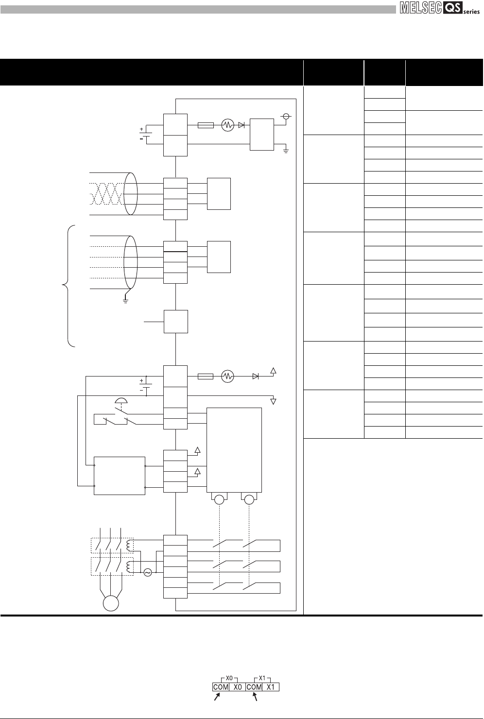
3 - 7
3.3 CC-Link Safety Relay Module Specifications
3.3.1 QS90SR2SP-CC CC-Link safety relay module
3
SPECIFICATIONS
* 3: When connecting an electromagnetic switch and such for output, connect its normally closed
contacts in series between XS0 and XS1.
* 4: Do not connect equipment other than a switch or sensor to each terminal of X0, X1, XS0, and XS1.
* 5: Common terminals for X0 and X1 differ. Pay attention to the printing on the module at wiring. In the
external connection diagram, they are represented as COM (X0) and COM (X1).
Table 3.4 Performance specifications of QS90SR2SP-CC (2/2)
External connection diagram Connector
Pin
number
Signal name
Module power
supply part
1
+24V
2
3
24G
4
CC-Link part
1DA
2DB
3DG
4SLD
Extension
communication
part
1EA
2EB
3EG
4EP
Safety power
supply, start-up
input part
1
XS0
*3*4
2
XS1
*3*4
3 +24V (SAFETY)
4 24G (SAFETY)
Safety input
part
1
COM(X0)
*5
2
X0
*4
3
COM(X1)
*5
4
X1
*4
Safety output
part 1
1Empty
2Z00
3Z10
4Z20
Safety output
part 2
1Empty
2Z01
3Z11
4Z21
Safety relay
Z21
M
Z20
Z11
Z10
Z01
MC0
MC1
Z00
Motor
EP
EG
EB
EA
COM(X1)
X1
X0
24G
(SAFETY)
+24V
(SAFETY)
24VDC (Safety
power supply)
24VDC (Module
power supply)
COM(X0)
24V IN
0V IN
Control
output 2
Control
output 1
XS1
XS0
MC0
MC1
Start-up
switch
24G
+24V
K1K0
Internal
safety circuit
24VDC
TH
0.9A
Fuse
5A
TH
0.9A
Fuse
5A
Monitor
circuit
GND
DC/DC
SLD
DG
DB
DA
CC-Link
circuit
Safety light curtain
OUT
Safety circuit part
extension cable
or
safety part terminating
connector
Connected to an
extension module
COM(X0) COM(X1)


