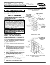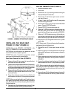
6
6. Perform one of the following:
A. Spring loaded seat guide: Remove the rear seat
guide and tension spring from the seat rail.
B. Plastic seat guide: Firmly grasp the plastic seat
guide and pull to remove from the seat rail.
7. Repeat STEPS 5-6 on remaining seat rail.
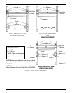
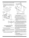
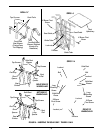
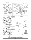
8. Slide one (1) medium spacer, solid seat bracet and
two (2) short spacers onto the right seat rail and se-
cure with tap screw as shown in FIGURE 7.
9. Slide one (1) solid seat brace and two (2) short spac-
ers onto the left seat rail and secure with tap screw
as shown in FIGURE 7.
10. Perform one of the following:
A. Spring loaded seat guide: Insert the tension spring
and the rear seat guide into the seat rail.
B. Plastic seat guide: Insert the the plastic seat guide
into the seat rail.
11. Insert the two (2) seat guides in to the two (2) seat
guide tubes.
NOTE: Ensure only 1/8-inch of the pivot bolt threads ex-
tend beyond the end of the locknut.
12. Reinstall the X-brace pivot screw and locknuts.
13. Slide a long spacer and solid seat brace onto the right
side seat rail and secure with a tap screwsas shown
in FIGURE 7.
14. Slide a long spacer and solid seat brace onto the left
side seat rail and secure with a tap screwsas shown
in FIGURE 7.
15. Secure the solid seat insert to the two (2) left solid
seat brackets with the four (4) long mounting screws.
NOTE: When conecting the right and left solid seat brack-
ets, tighten the bolts and locknuts enough to minimize
play, but still allow the solid seat braces to pivot when fold-
ing the wheelchair.
16. Secure the two (2) left solid seat braces to the two (2)
right solid seat braces with the two (2) bolts and lock-
nuts.
INSTALLING THE SOLID SEAT -
TRACER EX ONLY (FIGURE 7)
NOTE: Refer to the GENERAL WARNINGS in the
SAFETY SUMMARY of this Instruction Sheet.
NOTE: Right and Left sides of the wheelchair are de-
termined from the occupants position.
NOTE: Take note of orentation and position of seat
rear seat gides and hardware for reinstallation.
Solid Seat Ordered On Chair (FIGURE 7)
1. Remove the two (2) tap screws that secure the front
solid seat braces to the seat rails.
2. Remove the front solid seat braces from the seat rails.
Rotate the front solid seat braces upward and reinstall
onto the seat rails and secure with the two (2) tap screws
provided as shown in DETAIL "A" of FIGURE 6.
3. Remove the two (2) bolts and lock nuts that secure
the two (2) right solid seat braces to the two (2) left
solid seat braces.
4. Secure the solid seat insert to the two (2) left solid
seat brackets with the four (4) long mounting screws.
NOTE: When connecting the right and left solid seat brack-
ets, tighten the bolts and locknuts enough to minimize
play, but still allow the solid seat braces to pivot when fold-
ing the wheelchair.
5. Secure the two (2) left solid seat braces to the two (2) right
solid seat braces with the two (2) bolts and locknuts.
Solid Seat Ordered Off Chair (FIGURE 7)
1. If equiped with removable arms, remove arms from
the wheelchair.
2. Close chair.
3. Remove the eight (8) mounting screws securing the
seat upholsteryto the seat rails.
4. Remove X-brace pivot screw and locknut from X-
brace.
5. Lift one (1) seat rail UP until the seat guide is clear of
the guide tube.


