


27
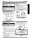
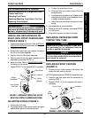
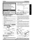
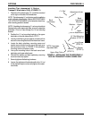
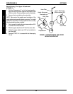
FIGURE 5 - INSTALLING/ADJUSTING THE FRONT ANTI-TIPPERS
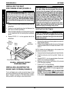
Adjusting Front Anti-tippers
1. Measure from the floor to the bottom of the wheels
of the triangular assembly.
2. Perform one (1) of the following:
TRIANGULAR ASSEMBLY 3/4-INCH FROM
FLOOR - Repeat STEP 1 for the opposite triangular
assembly.
TRIANGULAR ASSEMBLY
NOT 3/4-INCH FROM
FLOOR - Proceed to STEP 3.
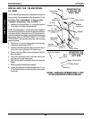
3. Remove the machine screw, washers and locknut
securing the triangular assembly to the bottom of
the anti-tipper arm.
4. Position the triangular assembly mounting hole to
align with one (1) of the adjustment holes in the anti-
tipper arm.
5. Measure from the floor to the bottom of the wheels
of the triangular assembly.
Machine
Screw
Washer
Locknut
Triangular
Assembly
Wheel
Adjustment
Holes
Mounting
Holes
ê
é
3/4-inch
FLOOR
Anti-Tipper Arm
6. Repeat STEPS 4-5 until the bottom of the wheels of
the triangular assembly measure approximately
3/4-inch from the floor.
7. Secure the triangular assembly to the bottom of the
anti-tipper arm with the machine screw, washers and
locknut.
WARNING
DO NOT overtighten the locknut securing the tri-
angular assembly to the bottom of the anti-tip-
per arm. Otherwise, anti-tipper arm will not swing
freely and the wheelchair may tip over, resulting
in injury or damage.
8. Tighten the locknut until the triangular assembly does
not rattle, but swings freely at the end of the anti-
tipper arm.
9. Repeat STEPS 1-2 for the opposite triangular as-
sembly.
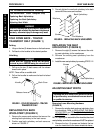
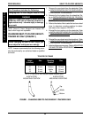
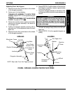
Bracket Clamps
Lug Bolts
Locknuts
Triangular Assembly
Front Caster
Attaches Here
(not shown for
clarity)
Wheelchair Frame
Anti-Tipper
Arm
NOTE: Right side Front Anti-Tipper pictured.
INSTALLING ADJUSTING
OPTIONS PROCEDURE 8
O
P
T
I
O
N
S