


15
This Procedure includes the following:
Swingaway Footrest Assembly Installation
Swingaway Footrest Height Adjustment
Heel Loop Replacement
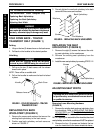
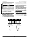
Elevating Legrest Assembly Installation
Adjusting the Elevating Legrest Assembly
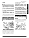
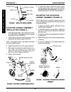
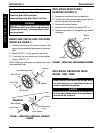
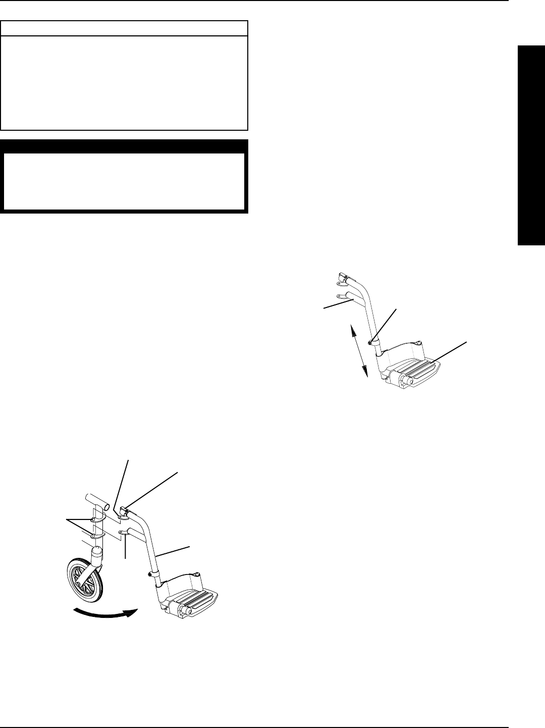
SWINGAWAY FOOTREST HEIGHT
ADJUSTMENT (FIGURE 2)
NOTE: Release the footrest locking mechanism and lift
the footrest off of the hinge pins. Lay the assembly on a
flat surface to simplify this procedure.
1. Remove impact guards and/or calf strap, if necessary.
2. Loosen, but do not remove the bolt and locknut that
secure the lower footrest assembly to the upper foot-
rest support.
3. Reposition the lower footrest assembly to the desired
height.
4. Securely tighten the bolt and locknut.
5. Repeat this procedure for the other footrest, if neces-
sary.
6. Replace impact guards and/or calf strap, if necessary.
WARNING
After ANY adjustments, repair or service and
BEFORE use, make sure all attaching hardware
is tightened securely - otherwise injury or dam-
age may result.
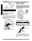
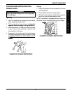
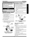
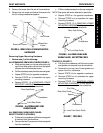
SWINGAWAY FOOTREST ASSEMBLY
INSTALLATION (FIGURE 1)
1. Turn the footrest to the side (open footplate is per-
pendicular to wheelchair).
2. Install the hinge plates on the footrest onto the hinge
pins on the wheelchair frame.
3. Push the footrest towards the inside of the wheel-
chair until it locks into place.
NOTE: The footplate will be on the inside of the wheel-
chair when locked in place.
4. Repeat this procedure for the other footrest assembly.
5. To release the footrest, push the footrest release le-
ver inward, rotate footrest outward.
Swingaway
Footrest
Assembly
Hinge
Plate
FIGURE 1 - SWINGAWAY FOOTREST
ASSEMBLY INSTALLATION
Footrest
Release
Lever
Hinge Plate
Hinge Pins
FIGURE 2 - SWINGAWAY FOOTREST HEIGHT
ADJUSTMENT
Upper
Footrest
Support
Bolt and
Locknut
Lower
Footrest
Assembly
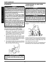
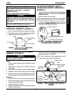
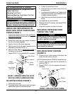
HEEL LOOP REPLACEMENT
(FIGURE 3)
NOTE: Heel loops are not available on Invacare MG
wheelchairs.
1. Loosen, but do not remove the bolt and locknut that
secure the lower half of the footrest to the swingaway
footrest assembly.
2. Remove the lower footrest assembly.
3. Remove the phillips screw and locknut that secure
the heel loop to the footrest.
4. Slide heel loop over cane of the footrest assembly.
5. Replace heel loop.
6. Reverse STEPS 1-5 to reassemble.
NOTE: When securing the heel loop to the footrest as-
sembly, tighten the phillips screw and locknut until the
spacer is secure.
F
R
O
N
T
R
I
G
G
I
N
G
S
PROCEDURE 1
FRONT RIGGINGS