


24
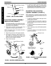
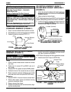
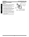
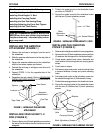
WHEEL LOCK ADJUSTMENT
(FIGURE 4)
NOTE: Before adjusting or replacing the wheel lock
assemblies, ensure that the tires are inflated to the
recommended psi on the side wall of tire.
1. Loosen the bolt and locknut that secure the wheel
lock assembly to the wheelchair frame.
2. Adjust the position of wheel lock until the mea-
surement between the rear wheel and the wheel
lock shoe is between 5/32 and 5/16-inches.
3. Securely tighten the bolt and locknut.
4. Engage wheel lock and push against the wheel-
chair and determine if wheel lock engages the
wheel lock shoe enough to hold the wheelchair.
5. Repeat the above procedures until the wheel lock
holds the wheelchair.
6. Repeat STEPS 1-5 for the opposite wheel lock.
Wheel Lock Handle
Bolt and Locknut
Rear
Wheel
Wheel Lock
Shoe
5/32 and 5/16-inches
FIGURE 4 - WHEEL LOCK ADJUSTMENT
ANTI-TIPPERS/WHEEL LOCKSPROCEDURE 7
A
N
T
I
-
T
I
P
P
E
R
S
W
H
E
E
L
L
O
C
K
S