


26
O
P
T
I
O
N
S
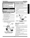
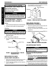
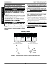
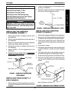
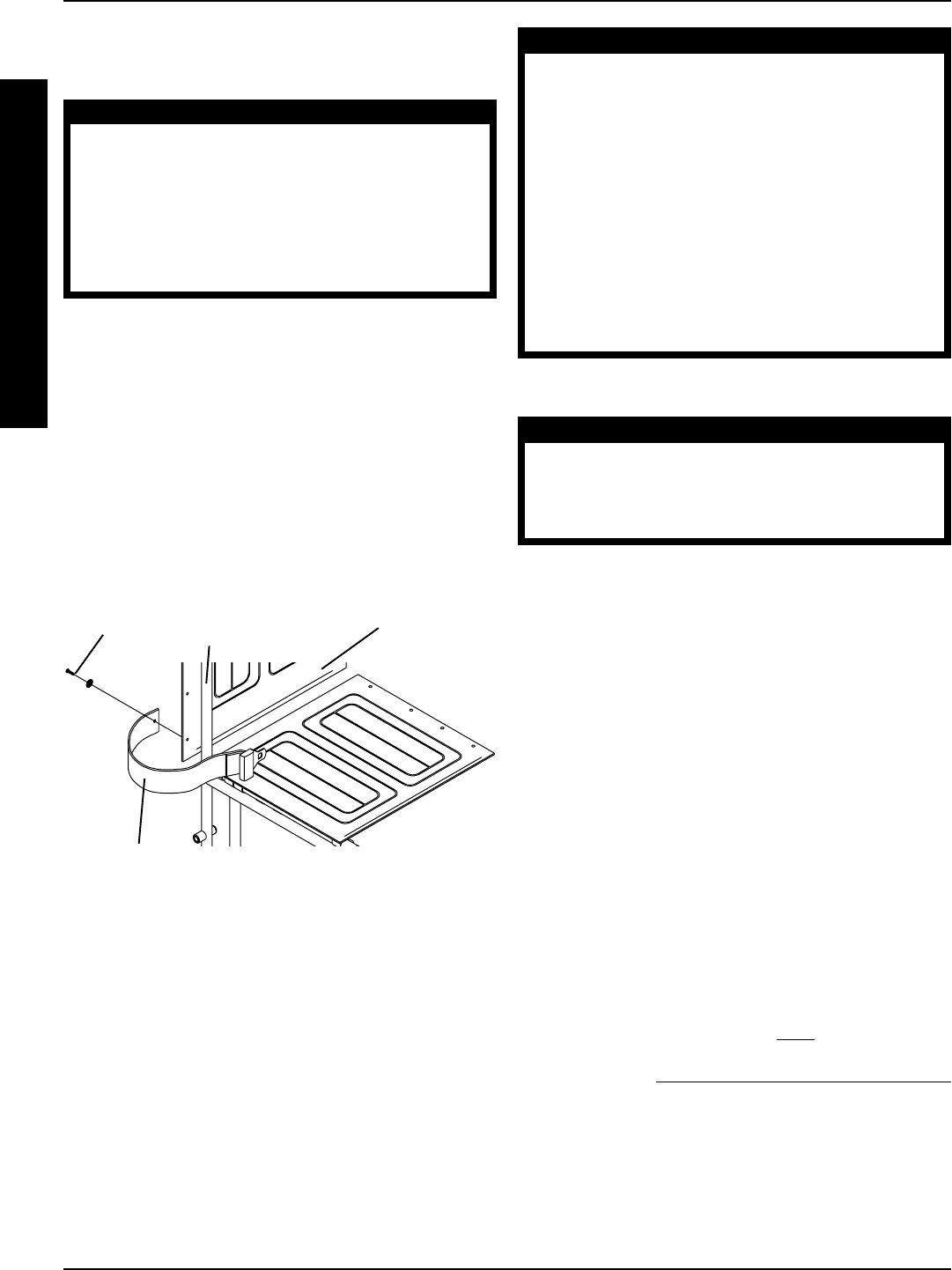
INSTALLING THE SEAT
POSITIONING STRAP (FIGURE 4)
WARNING
ALWAYS wear your positioning strap. Inasmuch
as the SEAT POSITIONING STRAP is an option on
this wheelchair (You may order with or without
the seat restraint), Invacare strongly recom-
mends ordering the SEAT POSITIONING STRAP
as an additional safeguard for the wheelchair
user.
1. Remove the bottom back upholstery screw from the
wheelchair.
2. Position the seat positioning strap half between the
back cane and back upholstery.
3. Secure the back upholstery and seat positioning strap
to the wheelchair with the existing back upholstery
screw.
4. Repeat STEPS 1-3 for the opposite side of the
wheelchair.
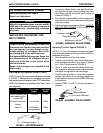
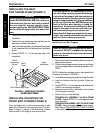
PROCEDURE 8
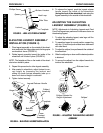
INSTALLING/ADJUSTING THE
FRONT ANTI-TIPPERS (FIGURE 5)
Front anti-tippers are a safe convenient way to help
prevent the wheelchair from tipping forward. The anti-
tipper "triangle" is always in the downward position;
when pivoted it will swing to clear obstructions.
FIGURE 4- INSTALLING THE SEAT
POSITIONING STRAP
Back
Cane
Back
Upholstery
Back
Upholstery
Screw
Seat Positioning Strap
OPTIONS
WARNING
Front anti-tippers are recommended by Invac-
are when using elevating legrests. Even though
a wheelchair is equipped with front anti-tippers,
individuals should be taught to elevate legrests,
swing front riggings aside and/or flip up footplates
so they are out of the way BEFORE placing feet
firmly on the floor when entering or exiting the
wheelchair. This will permit individuals to stand
close to front edge of the seat and lower him-
self/herself well enough back onto the seat.
Ensure Front Anti-Tippers are adjusted to the same
height - otherwise the wheelchair may tip to one
side and injury or damage may occur.
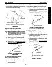
Installing Front Anti-Tippers
CAUTION
When securing the front anti-tippers to the wheel-
chair frame. DO NOT overtighten the attaching
hardware, otherwise damage to the wheelchair
frame may occur.
1. Remove the locknuts and the lug bolts from the anti-
tipper bracket clamps.
2. Position the anti-tipper bracket clamp over the wheel-
chair frame behind the front caster as shown in FIG-
URE 5.
NOTE: Position the anti-tipper arm on the outside of the
wheelchair as shown in FIGURE 5.
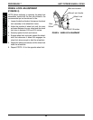
3. Squeeze bracket clamps together and insert the bolts.
4. Install the locknuts onto the lug bolts. Tighten se-
curely.
5. Repeat STEPS 1-4 on the opposite side of the wheel-
chair for the remaining anti-tipper.
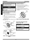
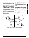
6. Measure from the floor to the bottom of the wheels
of the triangular assembly.
7. Perform one (1) of the following:
TRIANGULAR ASSEMBLY 3/4-INCH FROM
FLOOR - Repeat STEPS 1-2 for the opposite trian-
gular assembly.
TRIANGULAR ASSEMBLY
NOT 3/4-INCH FROM
FLOOR - Adjust the height of the triangular assem-
blies. Refer to
ADJUSTING FRONT ANTI-TIPPERS
in this section of the manual.