


25
This Procedure Includes the Following:
Installing the Amputee Attachment
Installing Fixed Height I.V. Rod
Installing the Carrying Pocket
Installing the Seat Positioning Strap
Installing/Adjusting the Front Anti-Tippers
Installing the Anti-Theft Device
WARNING
After ANY adjustments, repair or service and
BEFORE use, make sure all attaching hardware
is tightened securely - otherwise injury or dam-
age may result.
O
P
T
I
O
N
S
PROCEDURE 8
OPTIONS
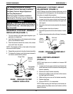
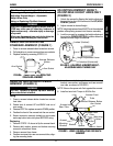
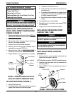
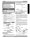
INSTALLING THE AMPUTEE
ATTACHMENT (FIGURE 1)
1. Remove the end cap or anti-tipper from the end of
the wheelchair.
2. Slide the amputee attachment over the step tube of
the wheelchair.
3. Secure the amputee attachment to the wheelchair
with the hew screw, spacer and locknut.
4. Reinstall the end cap or anti-tipper onto the end of
the wheelchair.
5. Repeat STEPS 1-4 for the opposite side of the
wheelchair.
6. Reposition the rear wheels. Refer to
REMOVING/
INSTALLING REAR WHEELS in PROCEDURE 4
of this manual.
FIGURE 1 - INSTALLING THE AMPUTEE
ATTACHMENT
Amputee
Attachment
Hex Screw
Spacer
Locknut
Step Tube
End Cap
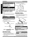
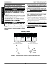
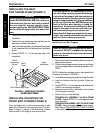
2. Position the socket mount on the wheelchair frame
as shown in FIGURE 2.
3. Secure the socket mount to the wheelchair frame
with the two (2) back upholstery screws.
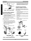
FIGURE 2 - INSTALLING FIXED HEIGHT I.V. ROD
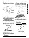
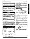
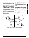
INSTALLING THE CARRYING
POCKET (FIGURE 3)
1. Determine the height required for the carrying pocket.
2. Remove the two (2) back upholstery screws and two
(2) washers that correspond to the desired height.
3. Center pouch against back canes, determine and
mark location for mounting holes on carrying pouch
straps.
4. Punch holes in straps.
5. Fold excess strap ends under, mark mounting holes
in second thickness of strap and punch mounting
holes.
6. Fold strap ends under so the upholstery screw can
be inserted through two (2) thicknesses of strap.
7. Position the carrying pocket on the wheelchair frame.
8. Secure the carrying pocket to the wheelchair frame
with the two (2) washers two (2) back upholstery
screws.
Socket Mount
I.V. Rod
Back
Upholstery
Screws
INSTALLING FIXED HEIGHT I.V.
ROD (FIGURE 2)
1. Remove the top two (2) back upholstery screws from
the side of the wheelchair that the socket mount was
designed.
FIGURE 3- INSTALLING THE CARRYING POCKET
Carrying Pocket
Back Upholstery Screws
Upholstery
Screws
Strap
Washer
Punched
Hole