


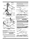
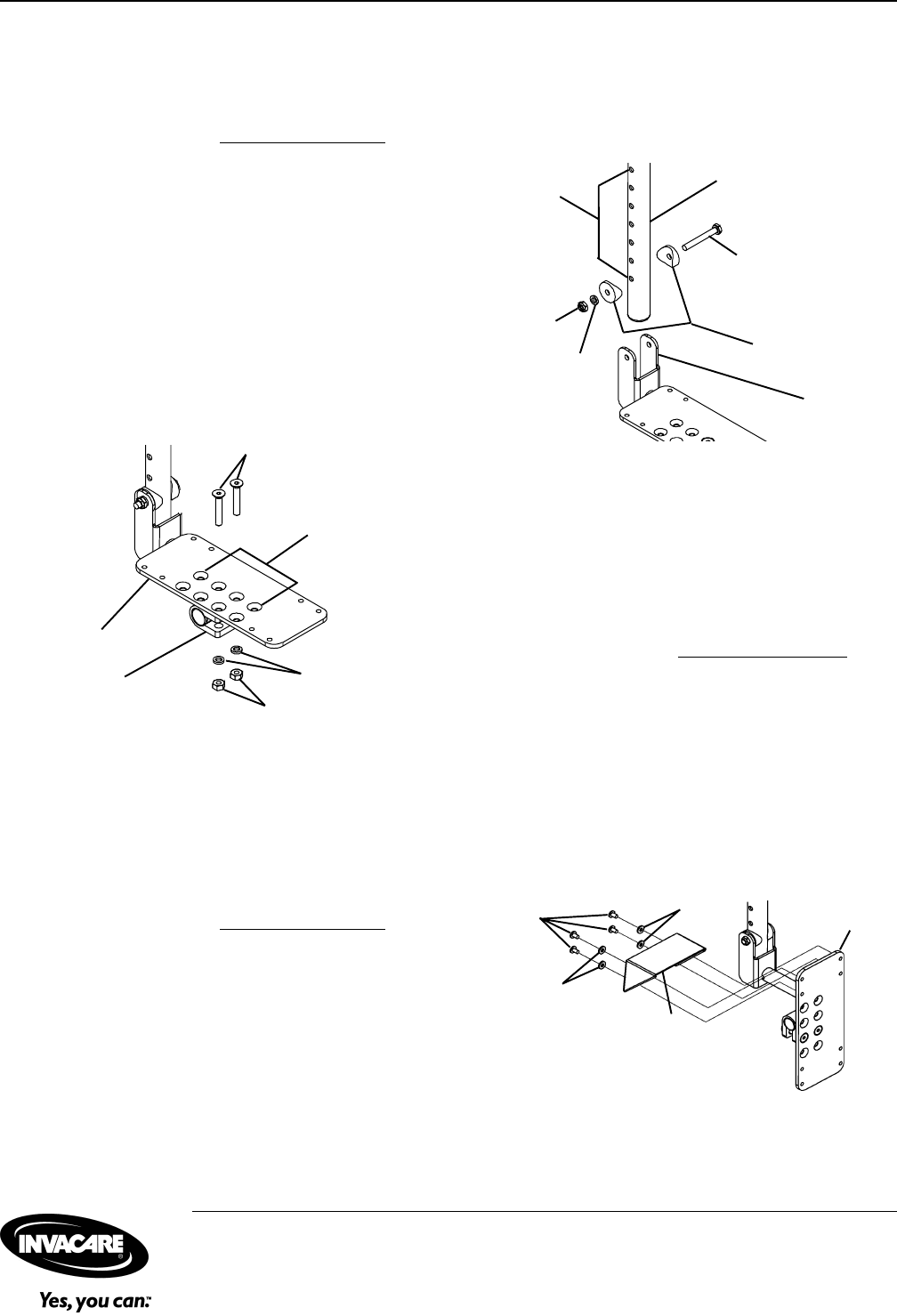
FIGURE 8 - CONTRACTURE FOOTPLATE HEIGHT
ADJUSTMENT
Mounting Screws
Lock Nut
Washers
Footplate
Bracket
Contracture Support
Coved Washers
Mounting
Holes
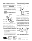
REPLACING THE CONTRACTURE
FOOTPLATE HEEL LOOP (FIGURE 9)
NOTE: Refer to the GENERAL WARNINGS and INSTAL-
LATION WARNINGS in the
SAFETY SUMMARY of this
instruction sheet.
1. Tilt the contracture footplate forward to gain access to the
mounting screws that secure the heel loop to the under-
side of the contracture foootplate. Refer to angle adjust-
ment of the contracture footplate in this instruction sheet.
2. Remove the four (4) mounting screws and washers
that secure the EXISTING heel loop to the contrac-
ture footplate.
3. Reverse STEPS 1-2 to install the NEW heel loop.
FIGURE 9 - REPLACING THE CONTRACTURE
FOOTPLATE HEEL LOOP
Invacare Corporation www.invacare.com
USA Canada
One Invacare Way 5970 Chedworth Way Invacare and "Yes, you can" are trademarks of Invacare
Elyria, Ohio USA Mississauga, Ontario Corporation.
44036-2125 L5R 3T9, Canada © 2000 Invacare Corporation
800-333-6900 905-890-8838 Form No. 00-97 Part No. 1095349 Rev A (1) 5/00
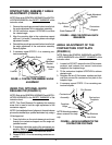
CONTRACTURE FOOTPLATE
HEIGHT ADJUSTMENT (FIGURE 8)
NOTE: Refer to the GENERAL WARNINGS and INSTAL-
LATION WARNINGS in the
SAFETY SUMMARY of this
instruction sheet.
1. Remove the mounting screw, two (2) coved washer,
washer and locknut that secure the footplate bracket
to the contracture support.
2. Move the footplate bracket UP/DOWN to achieve
desired height.
3. Align the mounting hole in the footplate bracket with
one (1) of seven (7) mounting holes on the contrac-
ture support.
FIGURE 7 - CONTRACTURE FOOTPLATE DEPTH
ADJUSTMENT
Contracture
Footplate
Flat Screws
Washers
Footplate Hinge
Lock Nuts
Mounting
Hole
Contracture
Footplate
Washers
Heel Loop
Mounting
Screws
Washers
CONTRACTURE FOOTPLATE
DEPTH ADJUSTMENT (FIGURE 7)
NOTE: Refer to the GENERAL WARNINGS and INSTAL-
LATION WARNINGS in the
SAFETY SUMMARY of this
instruction sheet.
NOTE: Observe the angle of the contracture footplate for
reinstallation.
1. Remove the two (2) flat screws, washers and lock-
nuts that secure the contracture footplate to the
footplate hinge.
2. Move the contracture footplate to one (1) of four (4)
mounting hole.
3. Reinstall the two (2) flat screws, washers and lock-
nuts that secures the contracture foot plate to the
footplate hinge.
4. Secure the footplate bracket to the contracture sup-
port with the mounting screw, two (2) coved washers,
washer and locknut. Securely tighten.
5. If necessary repeat STEPS 1-4 on remaining con-
tracture footplate.