


3
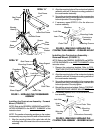
CONTRACTURE ASSEMBLY ANGLE
ADJUSTMENT (FIGURE 4)
NOTE: Refer to the GENERAL WARNINGS and INSTAL-
LATION WARNINGS in the SAFETY SUMMARY of this
instruction sheet.
1. Remove the mounting screw and locknut used to lock
the angle adjustment of the contracture assembly.
2. Lift the contracture support UP/DOWN to achieve
the desired angle.
3. Align the mounting hole in the contracture support
with one (1) of seven (7) mounting holes on the angle
adjustment bracket.
4. Reinstall the mounting screw and locknut used to lock
the angle adjustment of the contracture assembly.
Securely tighten.
5. If necessary repeat STEPS 1-4 on remaining con-
tracture assembly.
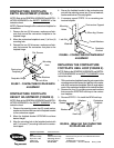
ANGLE ADJUSTMENT OF THE
CONTRACTURE FOOTPLATE
(FIGURE 6)
NOTE: Refer to the GENERAL WARNINGS and INSTAL-
LATION WARNINGS in the
SAFETY SUMMARY of this
instruction sheet.
1. Loosen, but DO NOT, remove the two (2) flat screws,
washers and locknuts that secure contracture
footplate to the footplate hinge.
2. Tilt the contracture footplate UP/DOWN to achieve
desired angle.
3. Retighten the two (2) flat screws, washers and lock-
nuts that secures the contracture foot plate to the
footplate hinge.
4. If necessary repeat STEPS 1-3 on remaining con-
tracture footplate.
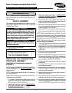
FIGURE 4- CONTRACTURE ASSEMBLY ANGLE
ADJUSTMENT
FIGURE 6 - ANGLE ADJUSTMENT OF THE
CONTRACTURE FOOTPLATE
Angle
Adjustment
Bracket
Mounting
Hole
Locknut
Contracture Support
Mounting Screw
Contracture
Footplate
Flat Screws
NOTE: Mounting hardware
shown removed for clarity
only.
Washers
Footplate
Hinge
Lock Nuts
Contracture
Assembly
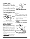
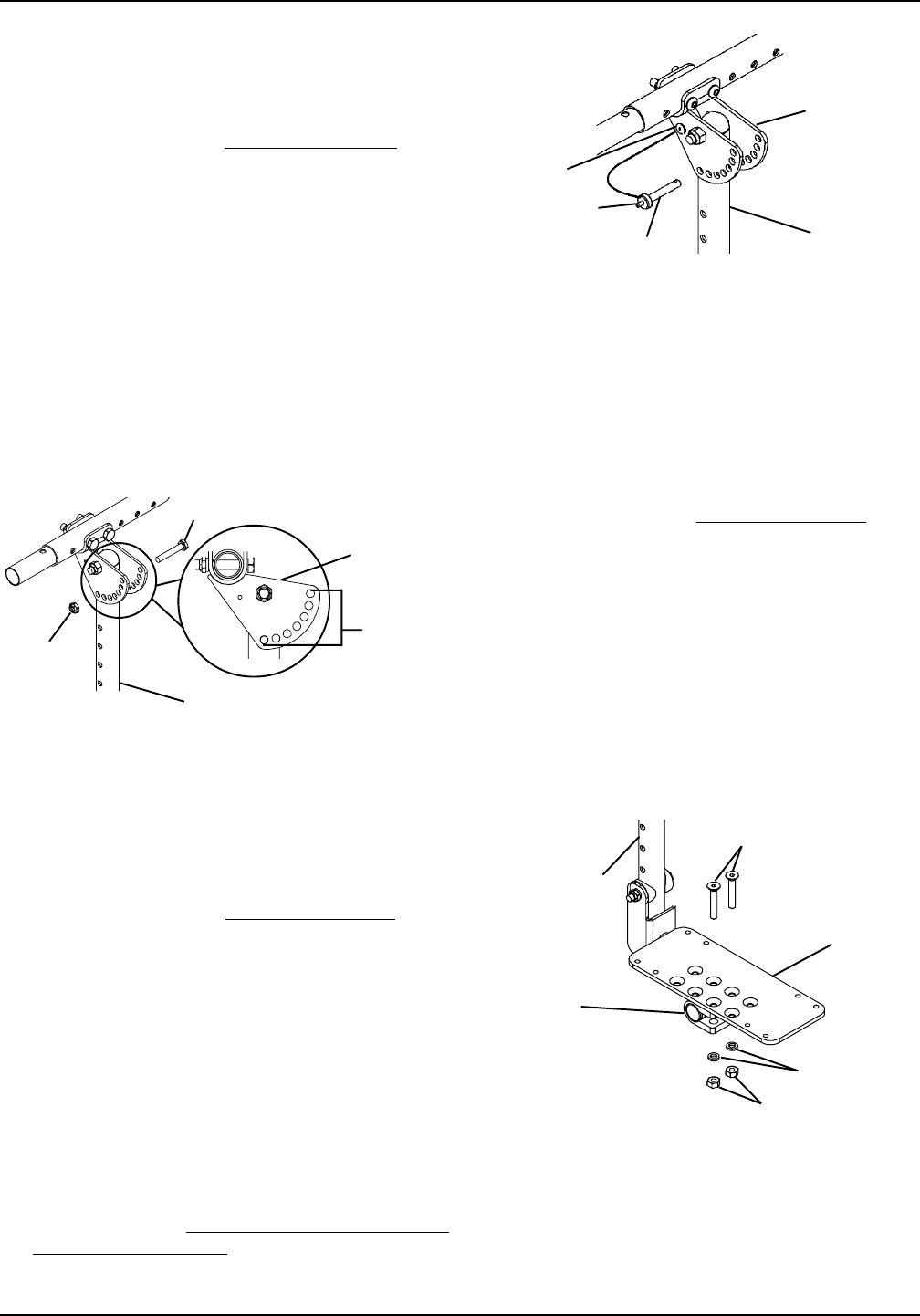
USING THE OPTIONAL QUICK
RELEASE PIN (FIGURE 5)
NOTE: Refer to the GENERAL WARNINGS and INSTAL-
LATION WARNINGS in the
SAFETY SUMMARY of this
instruction sheet.
NOTE: The Quick Release Pin replaces the mounting
screw that is used to lock the angle adjustment of the
contracture support.
NOTE: If not installed at time of shipment, the quick release
pin must be installed by a qualified technician only, using a
1/8-inch pop rivet.
1. Press the button on the quick release pin and insert
through the contracture support and the angle ad-
justment bracket.
2. If necessary adjust the angle of the contracture as-
sembly. Refer to CONTRACTURE ASSEMBLY
ANGLE ADJUSTMENT in this instruction sheet.
3. Repeat STEPS 1-2 on the remaining contracture as-
sembly.
FIGURE 5 - USING THE OPTIONAL QUICK
RELEASE PIN
Quick Release Pin
Angle Adjustment
Bracket
Contracture
Support
Button
Pop Rivet