


DISASSEMBLY
WARNING:
DISCONNECT THE AIR SUPPLY HOSE BEFORE PERFORMING MAINTENANCE ON THIS HOIST.
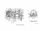
Note: Refer to the illustrations on the following pages. Disassemble the Hoist only as far as necessary to service the worn
or broken component.
1.
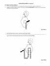
The Brake Piston (99) located in the Piston Housing (96) may be serviced by removing the Plate Screws (104). Plate
(103), Shoulder Bolts (105) and Lock Washers (106).
2.
Place the Piston Housing Assembly and Pressure Plate (98) down on a press table. Compress the Springs between the
Pressure Plate and the Housing and remove the Piston Nut (102). WARNING: Release the pressure of the Springs care-
fully.
3.
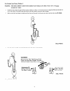
Push the Brake Piston (99) from the Housing.
Note: It is necessary to remove the Brake Driver Retainer (67) before the motor components can be removed.
4.
Remove the Muffler Cover Screws (33) and the Valve Chest Cover Screws (45).
5.
Remove the Valve Chest Screws (19) and remove the Valve Chest (16) from the Housing(l). Note: The Throttle Disc
Seals (58) and Seal Expanders (59) are free to fall from the Throttle Disc (57) as the Valve Chest is removed.
ASSEMBLY
Before assembling the Hoist clean and apply a light film of oil or grease where specified, to each part. Apply a thin film of
O-ring lubricant to each O-ring before final assembly. Clean and lubricate the load chain each time maintenance is performed
in addition to the regular maintenance schedule.
Assembly of Valve Chest End
1.
2.
3.
4.
5.
6.
7.
8.
9.
10.
11.
12.
13.
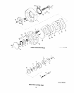
Install the Motor Shaft Front Retaining Ring (66)
onto the Motor Shaft (64) and slide the Front End Plate Bearing
(75) Front End Plate (74), bearing diameter first, and Rotor (70) small diameter first, onto the Shaft.
Apply a light film of oil to each Vane (71) slide one Vane into each slot and slide the Cylinder (72) over the Rotor.
Slide the Rear End Plate (69) and Rear End Plate Bearing (68) over the short end of the Motor Shaft and apply the Mo-
tor Shaft Rear Retaining Ring (65).
Align the holes in the Front and Rear End Plates with the dowel hole in the Cylinder and slide a l/8” diameter rod
12” long through the aligned parts.
Place the Motor Retaining Washer (76), dished (concave) side first, over the Front End Plate and engage the dowel hole
with the rod.
Slide the long hub of the Motor Shaft into the Housing(l), insert the guide rod into the pilot hole in the Housing and
seat the motor.
Remove the guide rod and replace it with the Cylinder Dowel (73).
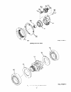
Apply the Housing Gasket (9) onto the motor end of the Housing and apply the Valve Plate (60) over the Gasket.
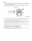
Apply a heavy film of O-ring lubricant to the Throttle Disc Seals (58) and the Seal Expanders (59). Insert an Expander,
small diameter first, followed by a Seal, into each of the two recesses in the Throttle Disc (57).
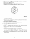
With the valve ports oriented as illustrated on Page 20, slide the Throttle Disc over the hub of the Rear End Plate.
With the Throttle Shaft (34) in place in the Housing(l), slide the Limit Gear (36) onto the keyed end of the Shaft and
engage the teeth on the Gear with those on the Throttle Disc.
For Hoists equipped with Pull Chain Throttle, apply the Throttle Shaft Spring (42) into the Valve Plate before install-
ing the Limit Gear.
For Hoists equipped with Pendent Throttle:
a. Install one Pendent Piston Seal (22), cupped side trailing, onto the Pendent Piston (21). Push the Piston through the
bore of the Valve Chest to the opposite side and install the remaining Seal cupped side outward.
b. Apply the Piston Rod Seal (24) to the Piston Rod (23) and slide the Rod into the bore of the Piston so the ends of
the Rod protrude equally beyond the Piston.
c. Slide a Piston Spring Retainer (27), small diameter trailing, followed by a Spring (26) over the ends of the Rod.
d. Align the hole in the Piston with the slot in the back of the Valve Chest.
e. Insert the Piston Drive Pin (25) into the Piston through the slot in the Valve Chest. Install the Piston Cylinder
Caps (28).
11