


Page 14
Testing Millivoltage (mV) Function
To verify accuracy of the mV function, do the following.
1. Connect the Calibrator to the VΩ and COM inputs on the meter.
2. Turn the rotary switch to mV.
3. Set the calibrator for the voltage from step 1 to 3 in Table 3.
4. Compare the reading on the Meter display with the display reading in Table 3.
If the display reading falls outside of the range shown in Table 3, the Meter does not
meet specification.
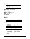
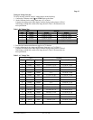
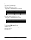
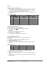
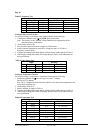
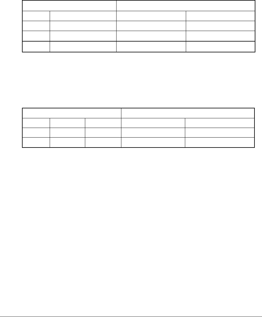
Table 3. DC mV Test
Input Reading
Step Voltage 61-633 61-635
1 36.000mV 35.848 to 36.156 35.894 to 36.102
2 -36.000mv -35.848 to -36.156 -35.894 to -36.102
3 360.00mV 359.08 to 360.92 359.58 to 360.42
5. Press the blue button on the Meter to toggle to AC mV function.
6. Set the calibrator for the voltage and frequency from step 1 & 2 in Table 4.
7. Compare the reading on the Meter display with the display reading in Table 4.
If the display reading falls outside of the range shown in Table 4, the Meter does
not meet specification.
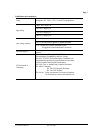
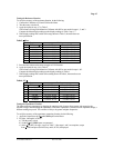
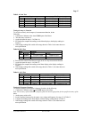
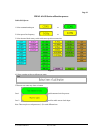
Table 4. AC mV Test
Input Reading
Step Voltage Frequency 61-633 61-635
1 360.00mV 50Hz 355.18 to 364.82 356.98 to 363.02
2 360.00mV 1KHz 352.30 to 367.70 355.90 to 364.10
Testing the PEAK HOLD Function
To verify operation of the PEAK HOLD feature, do the following.
1. Connect the Calibrator to the VΩ and COM inputs on the Meter.
2. Apply 1.0v ac rms at 60Hz from the Calibrator to the VΩ and COM inputs of the Meter.
3. Turn the rotary switch to V.
Note: The rms converter is not used in Peak Hold mode. The digital display represents the
actual peak value of the input.
4. Press (PEAK H) and then (M/M/A).
5. The reading on sub-display should be within 1.441 (Max) and -1.441 (MIN).
6. Press (PEAK H) to escape.
Form Number TM61633-5 Rev 5 Dec 2006