


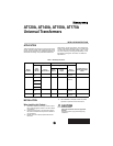
AT120A, AT140A, AT150A, AT175A UNIVERSAL TRANSFORMERS
Automation and Control Solutions
Honeywell International Inc. Honeywell Limited-Honeywell Limitée
1985 Douglas Drive North 35 Dynamic Drive
Golden Valley, MN 55422 Scarborough, Ontario M1V 4Z9
customer.honeywell.com
® U.S. Registered Trademark
© 2005 Honeywell International Inc.
69-0251-3 G.H. Rev. 06-05
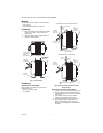
Mounting Through Outlet Box Knockout
The transformer can be mounted on an outlet box using
the clamp on the primary end bell. The mounting plate is
not used. To mount the transformer on an outlet box:
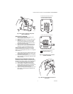
1. Turn the clamp screw almost all the way out.
2. From outside box, thread the primary leadwires
through suitable 7/8 in. knockout. Fit the clamp and
screw through the knockout. Do not mount the
transformer through a plastic knockout.
3. Tighten the clamp screw securely against the rim
of the knockout. Avoid damaging the leadwires
with the screwdriver.
WIRING
All wiring must comply with local codes and ordinances.
Disconnect power before making wiring connections to
prevent electrical shock or equipment damage.
1. Make primary connections to the line voltage
power supply. On multitap models, be sure to use
correct leads for available power supply. See
Fig. 6.
2. On multitap models, insulate the ends of the
unused leads using wire nuts or capping with a
solderless connector.
3. Make secondary connections to 24 Vac control
circuit.
CHECKOUT
CAUTION
Voltage Check Hazard.
Overload current protection is inherent on
AT120, AT140, and AT150. A fused 3.5 Amp
secondary is used on AT175.
Do not short transformer secondary terminals.
Voltage Check
After installation is complete, turn on power supply and
perform a voltage check:
1. Place controlled equipment in operation and
observe through one complete cycle.
2. Using a voltmeter, check for proper primary and
secondary voltages.
3. If voltage readings are incorrect, be sure primary
voltage connections are made correctly.
4. Measure voltage again:
a. If correct primary voltage is measured and
secondary voltage is significantly less than the
voltage shown on the regulation curves,
transformer winding is damaged. Replace
transformer and repeat checkout procedures.
b. If primary voltage is 0V, be sure power supply
is connected correctly or repair, if necessary.
Repeat checkout procedures.
5. Do not put system into operation unless correct
primary and secondary voltages are measured.
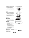
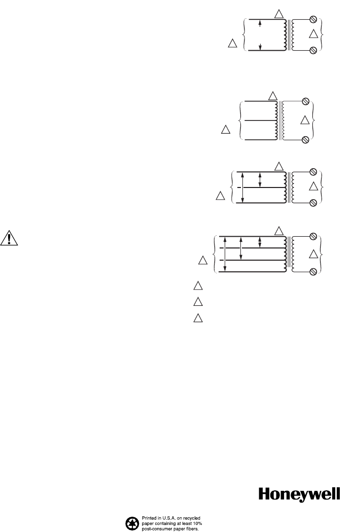
Fig. 6. Schematics for single and multitap
transformers.
VOLTAGE
VARIES
WITH MODEL
2
SECONDARY
M22974
COMMON
PRIMARY
BLACK
120 V - WHITE
208 V - RED
240 V - ORANGE
277 V - BROWN
480 V - BLACK/RED
1
3
SINGLE VOLTAGE MODELS
208 V
2
SECONDARY
COMMON
PRIMARY
BLACK
ORANGE
1
3
208/240 VAC MODELS
240 V
RED
208 V
120 V
2
SECONDARY
COMMON
PRIMARY
BLACK
ORANGE
1
1 SECONDARY CONNECTIONS ARE SCREW TERMINALS, 1/4 INCH
QUICK-CONNECTS OR BLUE AND YELLOW LEADWIRES.
BLACK IS COMMON WITH RESPECT TO THE TRANSFORMER
WINDING ONLY AND NOT THE EXTERNAL CIRCUIT.
SOME MODELS AVAILABLE WITH 1/4 INCH QUICK CONNECTS.
2
3
3
120/208/240 VAC MODELS
240 V
RED
WHITE
COMMON
BLACK
120 V
WHITE
240 V
ORANGE
PRIMARY
SECONDARY
3
1
2
120/240 MODELS