


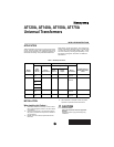
AT120A, AT140A, AT150A, AT175A UNIVERSAL TRANSFORMERS
69-0251-3 2
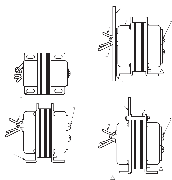
Mounting
The transformer can be mounted in one of three ways:
— foot mounting.
— plate mounting.
— mounting through outlet box knockout hole.
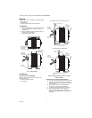
Foot Mounting
1. Mount the transformer using screws (not supplied)
through the four 3/16 in. x 3/8 in. holes in the
mounting feet.
2. Make line voltage primary connections within an
approved enclosure. See Fig. 1.
3. Discard the mounting plate.
Fig. 1. Foot mounting.
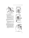
Plate Mounting
MOUNTING PLATE TO TRANSFORMER
Mount the plate to the transformer in either of two
positions (see Fig. 2):
• at clamp on primary end bell.
• at laminations.
Fig. 2. Mounting plate to transformer in either
of two positions.
MOUNTING PLATE AT CLAMP ON PRIMARY END BELL
1. Turn the screw on the clamp almost all the way out.
2. Hold the mounting plate with the keyhole slots up
and the raised portion of the large center knockout
away from you.
3. From the back, thread the primary leadwires
through the round center hole in the plate.
4. Fit the clamp and screw through the round hole.
5. While holding the plate in place, tighten the
setscrew securely against the rim of the hole.
See Fig. 3. Avoid damaging the leadwires with the
screwdriver.
USE SCREWS OR
BOLTS THROUGH
SLOTS (4) IN
MOUNTING FEET
SCREW TERMINALS
FOR SECONDARY
CONNECTIONS
MOUNTING
FOOT (2)
LEADWIRES
FOR PRIMARY
CONNECTIONS
M9161
PLATE MOUNTED AT CLAMP ON PRIMARY END BELL
MOUNTING
PLATE
MOUNTING PLATE
PLATE MOUNTED AT THE LAMINATIONS
M9162
END
BELL
CLAMP SCREW
AND CLAMP
RAISED PORTION OF
LARGE CENTER KNOCKOUT
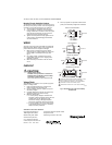
LEADWIRES
FOR PRIMARY
CONNECTIONS
LEADWIRES
FOR PRIMARY
CONNECTIONS
MOUNTING
SCREW
SCREW
TERMINALS FOR
SECONDARY
CONNECTIONS
SCREW
TERMINALS FOR
SECONDARY
CONNECTIONS
MOUNTING FEET ON "A" MODELS ONLY.
1
1
1