


17
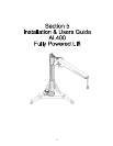
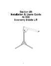
Section 6 - Installing the AL055 Economy Lift
• You should have established a mounting position for the lift during the “trial fit” as described in Section #2 of this
manual. If not, it is recommended that you go through that procedure.
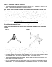
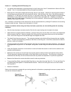
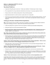
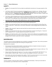
• Mount the lift in the location determined during the “trial fit” in the vehicle. Mark the 3 mounting hole locations or
use the Base as a guide and drill holes using a 3/8” drill bit. Bolt the Base to the floor of the vehicle using the
supplied 3/8” x 3” hex bolt in the corner, two 3/8” x 2” hex bolts for each Leg. Use the supplied multi-hole Installa-
tion Washers on the underside to help reinforce the vehicle’s floor, see Figure # 6.1. Replace an Installation
Washer with a 3/8” fender washer if necessary due to size constraints. Secure the Legs by tightening the 2 set
screws on the inside of the base.
Hint: Variations in the flatness of the vehicle’s floor can be compensated for by adding 3/8” washers to the mounting
hardware under the base. Always mount the base so it is level.
Caution! Avoid the vehicle wiring, fuel lines, fuel tanks, spare tires, etc. when drilling holes for mounting
hardware!
• Once the base has been mounted, place the Post into the nylon bushing that is located in the base.
• When the Post is properly seated in the Base, place the Lifting Arm onto the Post until it rests on the Adjustment
Collar located on the Post. Adjust the height of the Lifting Arm by loosening the hex screw on the Adjustment
Collar, move the Lifting Arm to the desired height and retighten the collar.
• The Hand Control has two plugs on it. The male plug attaches to the Vehicle Wiring Harness that was installed
earlier. The other, the female plug, attaches to the motor on the lifting arm. At this time, reconnect the vehicle’s
ground (-) cable on the battery.
• Tie the long leads of the Hand Control Harness to the Post using the plastic ties where necessary. This step will
be skipped when using the lift in a “Take Apart” configuration, as the Lifting Arm and the Post must be disassem-
bled.
• Follow the Operator Instructions in this section to Load and Unload the scooter or chair from the vehicle to test
operation and clearances.
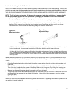
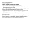
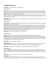
• Determine if the scooter or chair will need to be moved closer to the lift or further from the side of the vehicle.
This will be done by adjusting the location of the Strap Roller on the Lifting Arm. The Lifting Arm is factory pre-
assembled with the strap out at the furthest extent and may need to be adjusted to fit a particular application.
• Measure the distance the scooter should be moved to clear any obstacles.
• To move the Strap Roller, remove the Split Ring (like on a key chain) from the Clevis Pin. Pull out the Clevis Pin
and Strap Roller and replace it in the desired hole location. Holes on the Lifting Arm are on one inch centers.
See Figure #6.2
• Recheck all fasteners.
Refer to the instructions included with your docking device for information on preparing the scooter or power chair for
use with the Universal Inside Lift.
Figure # 6.1
Base Installation
Figure # 6.2
Adjustable Strap