


2D:4>6C:42?#65:42=&C@5F4ED25:G:D:@?@762=E9&C@5F4ED?4K#2EC:IK(,#2?F2= &
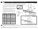
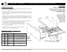
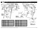
ccessory Assembly - 4” wide deck extension pan KIT
A
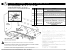
Item # Qty. Part # Description
1 1 999-0821-001G 4” Wide Kit Extension Pan
2 2 100-5225-009 1/4-20 x .75” Carriage Bolt
3 2 100-8525-001
1/4 Spring Lock Washer
4 2 999-0810-009 Black Pan Knob
5 2 100-7931-006 5/16 x 1.75” Clevis Pin w/Hole
6 2 100-2001-006
1-9/16 Hair Pin Clip
(Use existing)
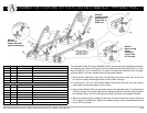
#$"$* 7-5=./;</6;
2C5H2C628
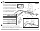
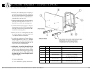
1. Raise the bed to a comfortable working height and elevate the knee deck to its highest
position. Now unplug the power cord.
2. Separate the footboard assembly from the main frame by removing the existing clevis
pins and hair pin clips. Put aside hardware. You will reuse the clevis pins and hair pin
clips in step 4 below.
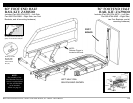
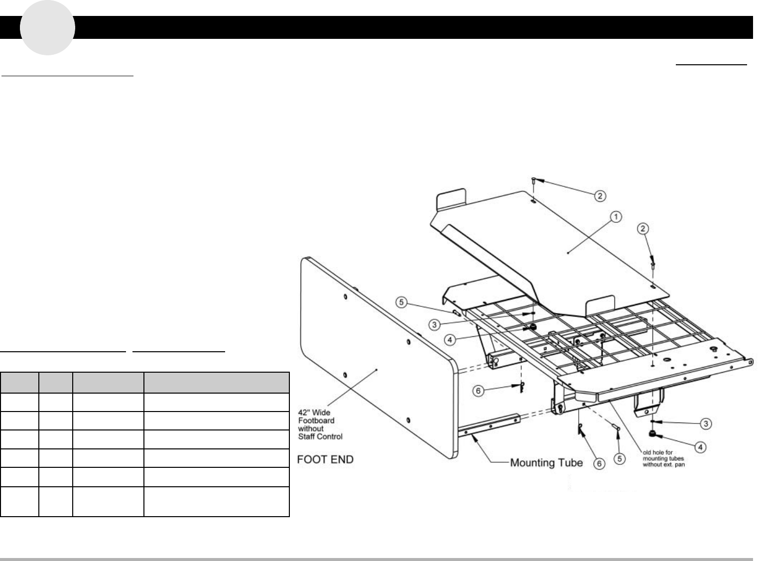
3. Attach the wide 4” extension pan (#1) to the foot deck by inserting the two 1/4-20 x .75”
Carriage Bolts (#2) from your hardware bag through the top designated holes and, from
the bottom, secure the pan tightly to the deck with two Spring Washers (#3) and two
Pan Knobs (#4).
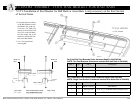
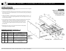
4. Now reinstall the footboard assembly by sliding the mounting tubes into the frame,
lining up the holes as shown (Note: The last hole in the tube will
now be one hole closer to the end of the main frame). Re-insert
the 5/16 x 1.75” clevis pins (#5) from the outside in and secure
with 1-9/16 hair pin clips (#6).
5. Replug the power cord and verify that all bed functions work
properly and all parts have adequate clearance.
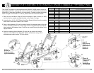
##)#$"%$ #
!$%"
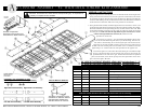
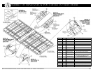
#2EC:I@@E?5H:E9
)E2?52C5"6G6=6C)EC2AD-:56
@@E3@2C52?5-:5664<
MIE6?D:@?&2?
$%*
*96IE6?D:@?&2?7@C
E96H:56564<:D24EF2==J
3:886C3@E9:?H:5E9
2?5=6?8E9E92?E96
DE2?52C56IE6?D:@?
A2?3FEDE:==@?=J
6IE6?5DE96365
564<7@FC:?496D
Reuse existing Hair Pin Clips