


Scorpion™ RVM/RGY/GVC User Manual (Rev. 01e) Page 23 of 24
DMX Cabling
The DMX protocol requires using special data cables to accommodate for the high speed
digital signals it uses. Despite their apparent similarities, data cables are electrically different
from standard microphone cable because they can carry high frequency digital signals and are
less prone to electromagnetic interference. You can purchase CHAUVET® certified DMX
cables directly from a dealer/distributor or make your own DMX cable.
If you choose to make your own DMX cable, you must use a data-grade cable such as the
Belden 9841, which has the following electrical characteristics:
Type: shielded, 2-conductor twisted pair
Maximum capacitance between conductors: 30 pF/ft
Maximum capacitance between conductor and shield: 55 pF/ft
Maximum resistance: 20 ohms/1000 ft
Nominal impedance: 100~140 ohms
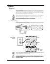
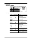
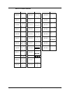
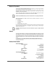
DMX Connectors
Each DMX cable must have a male XLR connector on one end and a female XLR connector on
the other end. The DMX protocol indicates that the XLR connectors must have five pins.
However, most lighting fixtures use the 3-pin XLR connector. The pin out of the 3-pin XLR
connectors in a DMX cable is a follows:
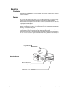
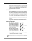
As it is common with digital signal links, the DMX daisy chain uses a terminator to reduce
signal transmission problems. This terminator consists of a 120 Ω, ¼ W resistor connected to
pins 2 and 3 of a male 3-pin XLR plug as shown below. This plug connects to the DMX Out
socket of the last DMX fixture in the daisy chain.
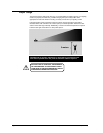
Do not allow the common wire of the DMX cable to come in contact with the fixture’s chassis
ground. This could cause a ground loop, which could make your fixture to perform erratically.
Test all DMX cables with an ohmmeter to verify the correct polarity of the wires and to make
sure that they are not shorted to the shield or to each other.
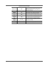
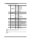
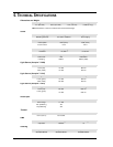
3- to 5-PinConversion Table
The table below illustrates the pin out for the 3- and 5-pin XLR connectors, which you could use
to make a 3- to 5-pin adapter.
Wire Usage
3-Pin XLR Connector
5-Pin XLR Connector
Shield (Common)
Pin 1
Pin 1
Data –
Pin 2
Pin 2
Data +
Pin 3
Pin 3
Not assigned
---
Pin 4
---
Pin 5
COMMON
DMX +
DMX -
INPUT
OUTPUT
1
3
2
1
3
2
1
3
2
120 ohm ¼ W resistor between
pin 2 (DMX -) and pin 3 (DMX +)
connected to the output of the
last fixture