3
INSTALLATION
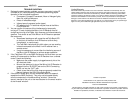
This unit is meant to be installed into a standard J-Box mounting box and
interfaced to Xantech Connecting Blocks, such as the CB12, 789-44, 791-
44, etc.
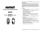
Figure 1 – WL series Assembly
CAUTION: THE J-BOX MUST NOT BE SHARED WITH 120/240VAC
CIRCUITS.
PLACEMENT
Placement of the IR Receiver does matter when used in the presence of a
Plasma Display. Ideally it should be placed somewhere around the Display
with the front of the receiver flush with the front of (or set back from) the
Display. If the WL85 needs to be placed in front of the display (such as on
an adjacent side wall perpendicular to the display), make sure it is placed at
a location at least 45 degrees off axis from the corners of the unit – see
Figure 2. The presence of Direct Sunlight and Fluorescent Lighting should
not affect the reception of this unit.
4
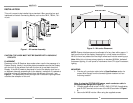
Figure 2 – WL series Placement
NOTE: Plasma interference can be reflected off of any item within approx. 3
feet from the front of the display. Keeping this in mind, make sure that the
WL85 is free of any obstruction that might reflect back into the receiving eye.
Note: While this unit shows strong rejection to standard 50/60Hz ‘ballasted’
fluorescent lighting, it is still prone to interference from CFL style Fluorescent
lighting.
MOUNTING
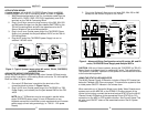
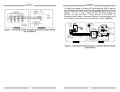
1. Pre-wire a 3-conductor cable (refer to Specifications section for
proper Wire Gauge) from the connecting block location to J-box
mounting location.
Note: If using the STATUS LED feature, use 4-conductor cable in
the appropriate gauge (see Figure 2)
2. Connect proper wires to the +12VDC, GND, STATUS (if applicable),
and IR OUT terminals on the rear of the WL85 as shown in Figure
2.
3. Secure the WL85 into the J-Box using the supplied screws.
45°
45°
PLASMA DISPLAY
780-95 Top View
WL85 TOP VIEW