12
OPERATION UNDER SHUTDOWN
Your UPS will shut down and the LCD will display a message if it detects one of the
following conditions. Note: For all conditions, the “Input,” “Output” and “Bypass” LEDs
will be illuminated.
Condition LCD Display Message
Extended Overload (>150%) OVERLOAD 150%
SHUT DOWN
Output Short Circuit SHORT CIRCUIT!
SHUT DOWN
Remote Shutdown Command REMOTE
(FROM DB9 INTERFACE) SHUT DOWN
Remote Shutdown Command EMERGENCY STOP!
(from RJ11 interface) SHUT DOWN
Internal Faults INVERTER TOO LO
SHUT DOWN
INVERTER TOO HI
SHUT DOWN
DC BUS +/- HIGH/LOW
SHUT DOWN
OVERTEMPERATURE
SHUT DOWN
OPERATION OF MANUAL BYPASS SWITCH
Turn this switch to “BY-
PASS” before performing
any maintenance on the
UPS with the connected
load supported. Connected
equipment will receive
filtered AC mains power,
but will not receive
battery power in the event
of a blackout.
SWITCHING UPS TO “BYPASS” MODE
• Turn the “ON/OFF” Switch OFF. (LCD will read "ON BYPASS.")
• Turn the “Manual Bypass” Switch clockwise from NORMAL to BYPASS.
• Turn the AC Input Circuit Breaker OFF.
• Open battery fuse holders and remove the battery fuses from all battery packs
and from all SU6K models.
SWITCHING UPS TO “NORMAL” MODE
• Replace all battery fuses in the battery fuse holders and close the
battery fuse holders.
• Turn the AC Input Circuit Breaker ON.
• Turn the “Manual Bypass” Switch counterclockwise from BYPASS
back to NORMAL.
• Turn the “ON/OFF” Switch ON.
Battery Charge Warning LCD Display Message
Battery charge nearly depleted BATTERY LOW
AC/DC charger not operating CHARGER FAILURE!
BATTERY CHARGE WARNINGS
Since your UPS can provide battery backup only for as long as the batteries remain
charged, these warnings should be acted on immediately.
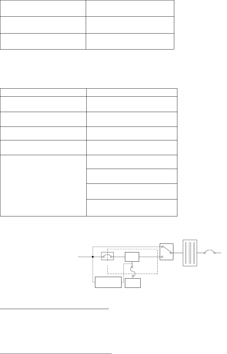
AC INPUT
UPS
¡¸LONG BACK-UP
TIME CHARGER
BATTERY
CABINET
UPS POWER
MANUAL BYPASS SWITCH
¡¸ LONG BACK-UP TIME MODELS CONTAIN LONG BACK-UP TIME CHARGE
¡¸ IN THE CONFINED AREA, ALL COMPONENTS ARE ELECTRIC ISOLATION
WITH AC LINE
INPUT BREAKER
OUTPUT BREAKER
OUTPUT
SUBP CHARGER OUTPUT
STD.
BATTERY
SUBP CONNECTED MODELS CONTAIN SUBP CHARGER
CURRENT IN THE AREA MARKED BY THE DASHED
OUTLINE. ALL COMPONENTS ARE ELECTRONICALLY
ISOLATED FROM THE AC LINE.


