12
Chapter 2 Start
2.1 Pin Definitions and Reference Layout
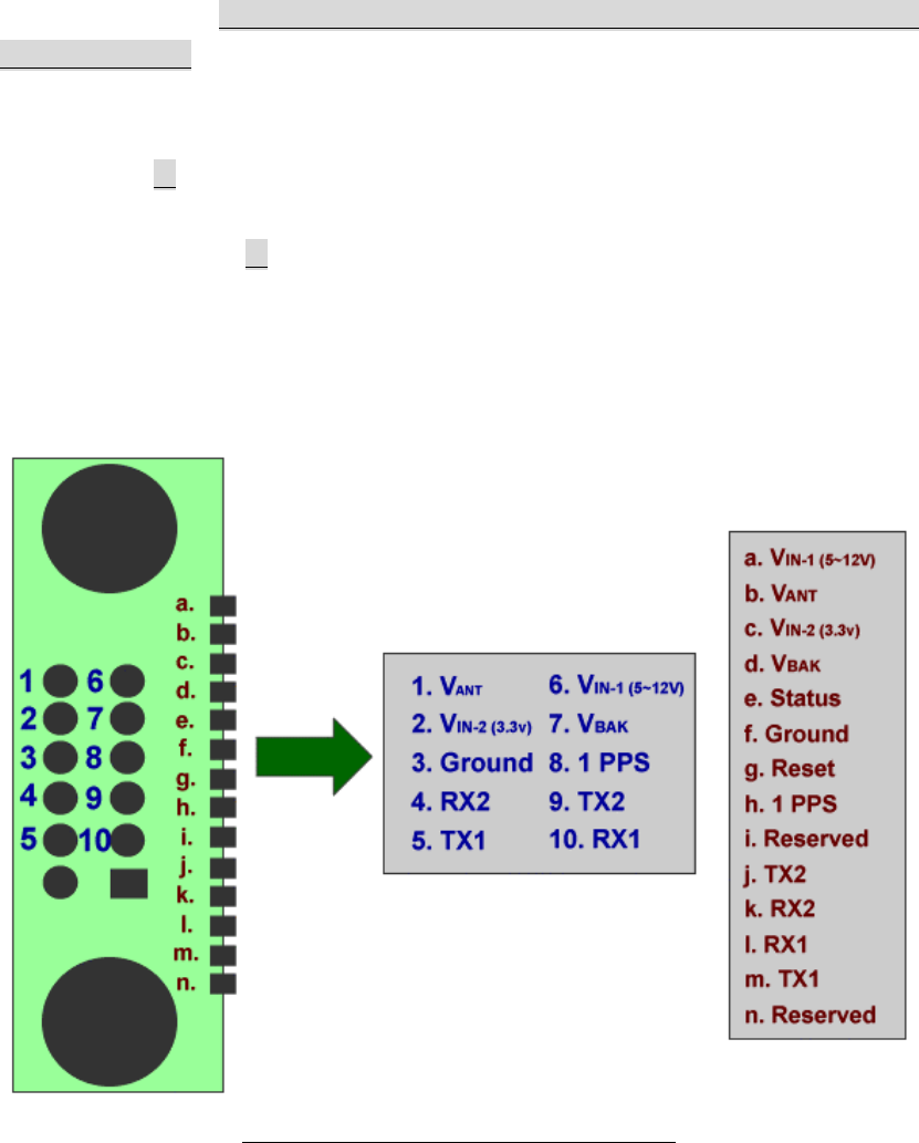
Figure 2.1 shows the pin definitions of FV-25. Table 2.1 describes the corresponding
definitions for pins. Note that only either use VIN-1 (DC 5 ~ 12V) or VIN-2 (DC 3.3V)
for voltage input. Also, if the Pins 1 ~ 10 are used, please leave Pins a ~ n being
opened. There are two comm. ports to input/output the useful information (i.e.
receiver’s and satellites’ data) for the users. The default setting for comm. 1 (either
Pins 5 and 10 or Pins l and m) is to input/output the information in the ASCII format,
which is NMEA with the default baud rate 4800 bps, and the default setting for comm.
2 ( either Pins 4 and 9 or Pins j and k) is to input/output the information in the binary
format, which is UBX (proprietary messages) with the default baud rate 4800 bps.
The protocols for NMEA and UBX sentences will be introduced in Chapter 7. All the
serial ports are operated at the level of 1.8 V.
Figure 2.1 FV-25 Pin definitions (Top View)


