25
4.4 Assembly 4. Maintenance
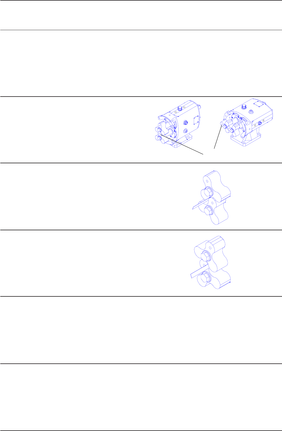
Step 2
Set the rotors (17) to the positions shown with the rotor dimples
in the 6-12 o’clock plane (horizontally ported pumps) or 3-9
o’clock plane (vertically ported pumps).
Step 3
Turn the shaft so that the rotors are in the new positions as
shown.
Step 4
Using feeler gauges measure between the points indicated,
turning the shaft as required.
Step 5
If the measurement points are unequal tap the rotor which is on the free turning shaft until equal measurement through 6 points
is achieved.
Step 6
Tighten the torque locking assemblies or clamp plate screws. Confirm timing is still correct. Remove the rotors.
Dimples
4.4.6 Adjusting rotor timing
Step 1
If the rotor timing requires adjustment (and assuming the pump has not yet been re-built), it is important to establish the cause for
the rotors mistiming before proceeding.
To allow timing adjustment ensure that one shaft is able to rotate within the torque locking assembly/element. The other torque
locking assembly/element should be tightened to the recommended torque.


