32
Connections and Settings
Chapter 3 Preparations
Using the editing functions of the
recorder (controlling through
REMOTE(9P) connector)
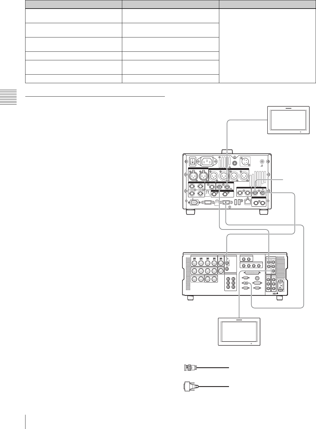
The following figure shows a cut editing system
comprising this unit as a player, and an HDW-M2000/
M2000P unit as a recorder. In this example, video and
audio signals are connected by HDSDI, and control signals
are transferred via the REMOTE(9P) connector.
REF.VIDEO INPUT connector 75 Ω
termination switch: OFF
Setup menu 01 PREROLL: 5s Setup menu item 214 REMOTE
INTERFACE: 9PIN
Audio selection function switching button
INPUT button: HDSDI
Setup menu 05 SYNC SEL: ON
Function menu HOME >F1 (VID. IN): SDI Setup menu 06 SYNC VTR:
RECORDER
Function menu page 1 >F1 (TCG): INT Setup menu 09 EDIT DLY: AUTO
Function menu page 1 >F2 (PR/RGN):
PRESET
Setup menu 10 R ST DLY:AUTO
Function menu page 1 >F3 (RUN): FREE Setup menu 11 P ST DLY:AUTO
HDW-M2000 (recorder) settings RM-280 (editing controller) settings Settings on this unit
75Ω
POWER
REMOTE(9P)VIDEO CONTROL
DC IN 12V
=
AC IN
REMOTE
ANALOG AUDIO INPUT
SDSDI OUTPUT
ANALOG AUDIO OUTPUT
12
12
(SUPER)
12
(SUPER)
12
AUDIO MONITOR
RL
1/2 3/4IN
1/2 3/4
OUT
DIGITAL AUDIO (AES/EBU) HDSDI INPUT HDSDI OUTPUT
12
(SUPER)
COMPOSITE OUTPUT
IN
REF.VIDEO INPUT
IN OUT
TIME CODE
S400
MAINTENANCE
REF.VIDEO
INPUT
REMOTE 1-OUT(9P)
HDSDI
OUTPUT 3
(SUPER)
REMOTE(9P)
REF.VIDEO
INPUT
REF VIDEO
INPUT
HDSDI
INPUT
HDSDI
OUTPUT2
(SUPER)
HDSDI
OUTPUT1
1
1
1
1
1
2
HD video monitor
To HDSDI input connector
PDW-HD1500
(this unit, player)
Reference
video signal
HDW-M2000
(recorder)
To HDSDI
input
connector
1: 75Ω coaxial cable (not supplied)
2: 9-pin remote control cable (not supplied)
HD video monitor


