ENFORCER FLUSH-MOUNT OUTDOOR ACCESS KEYPAD
ENFORCER FLUSH-MOUNT OUTDOOR ACCESS KEYPAD
WIRING – Auxiliary Accessories
a) Auto Relock – The door will relock after
granting access to prevent ―tailgate‖ entries.
b) Forced-Open Alarm – Alarm will go off
instantly if the door is forced open. Enable
this function with programming option 801
(found on pg.14).
c) Door-Propped-Open Alarm – Alarm will go
off if the door is left open longer than the
programmed delay time. Enable this
function with programming option 9
(1~999 seconds).
d) Mantrap (Interlock) Control – When the
door is open, the interlock output of the
keypad will switch to ground to disable the
other keypads.
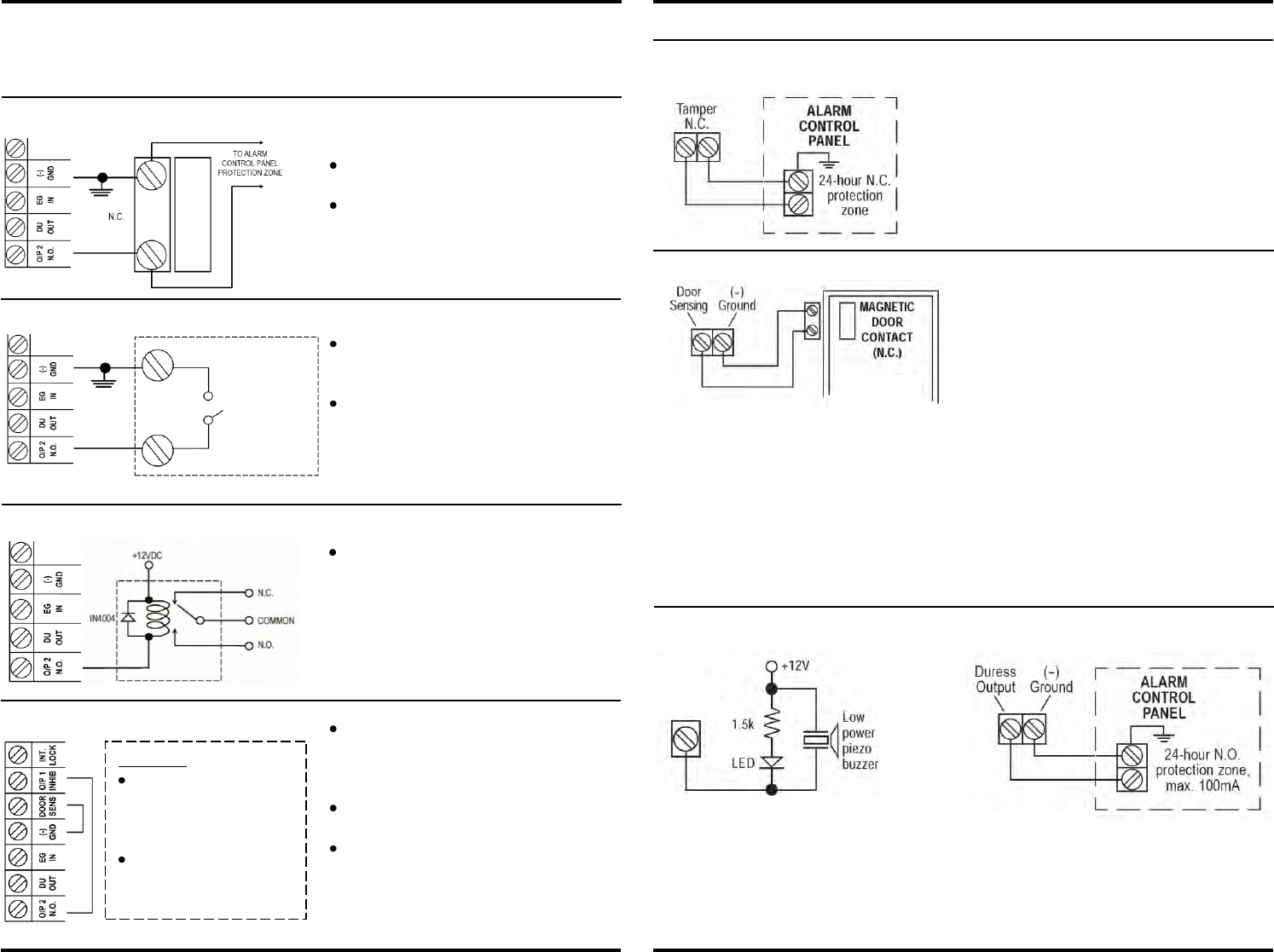
OUTPUT 2 (NPN TRANSISTOR OPEN COLLECTOR)
When the keypad is secured in the
single-gang box, the tamper switch is in the
closed position. When the keypad is
removed, the tamper switch will open.
Connect the terminals to a 24-hour N.C.
alarm system protection zone if required.
When a duress code is entered, the duress output will switch to (-) ground. It can trigger a
connected LED lamp or small buzzer to notify a guard, or connect it to a 24 hour N.O. alarm
system protection zone.
NOTE: Only one connection option is recommended. Output current must not exceed 100mA.
The Output 2 is an NPN transistor open collector output controlled by User Code 2, and can be
used for some auxiliary controls. It is equivalent to an N.O. output rated 100mA @24VDC.
1. Shunting an N.C. Protection Zone
Use output #2 to shunt an N.C.
protection zone.
Set output #2 to ON/OFF Mode
(See pg.14, section 3, programming
option 51).
2. Alarm System Arm-Disarm Control
Refer to your alarm control panel
manual to determine whether the arm-
disarm control is NC or NO.
Set output #2 to momentary mode for
multi station systems or ON/OFF mode
for single-station systems. See page
14, section 3 for programming options.
3. Drive an Optional Output Relay
Use a 12VDC relay and connect it to the
same 12V power supply as the keypad.
Using this setup, the owner may enter the
user code for output #2 to disable output
#1 during a certain period to prevent
unauthorized access.
Set output #2 to ON/OFF mode
(pg.14, section 3, programming option 51).
Connect the O/P 1 INHIB terminal with the
O/P 2 N.O. terminal as shown in wiring
diagram. User code #1 is invalid while the
O/P 1 INHIB terminal is shunted to ground
via user code #22.
WARNING
Make sure nobody is
inside the house before
starting the door lock
inhibit function.
The inhibit authorization
code should always be
kept by only the owner.
4. Connecting Inhibit Control
Terminals in Alarm
Control Panel for
Connecting Remote
Arm-Disarm Control
Switch
NO or NC Contact


