6 Pelco Manual C221M-C (6/03)
ᕥ
Install MR5000 Series Accessories
PCM5000 Light-Duty Camera Mount Assembly
a. The PCM5000 camera mount assembly can be installed on the top or bottom of the
MR5000M mount arm. To install the camera assembly onto the MR5000 Series
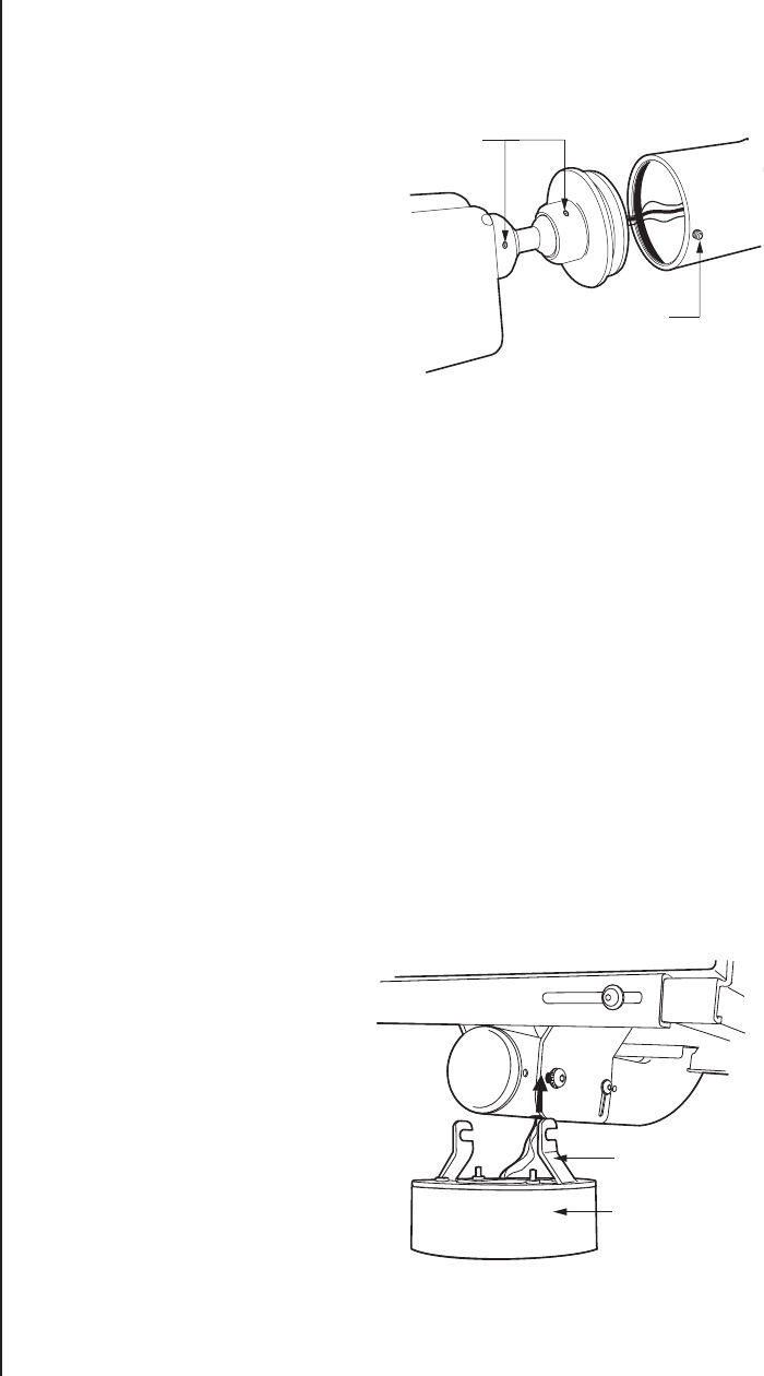
mount, refer to Figure 4 and do the following:
1. Pull video and electrical wire/
cable for the camera out
through the end of the mount
arm. Make all camera video
and electrical connections.
2. Place the end of the camera
assembly into the end of the
MR5000 Series monitor
mount arm. Tighten the set
screws to secure the camera
assembly.
b. Refer to the manuals supplied with
the camera and the PCM5000 for
detailed installation and operation
instructions.
ICS-DO101ABK Camclosure Integrated Camera System
a. Refer to Figure 5 and do the following to attach the adapter plate of the ICS-DO101ABK
to the base of the ICS-DO101ABK:
1. Align the adapter plate to the base of the ICS-DO101ABK.
2. Use the two 10-32x .375-inch, pan head screws and internal lock washers to
attach the base of the ICS-DO101ABK to the adapter plate.
b. Prepare the video and electrical cabling for the ICS-DO101ABK:
1. Feed the 42-inch video cable (provided) through the monitor feedthrough hole in
the mount arm and out the end of the mount arm.
2. Pull power wires through the ICS-DO101ABK feedthrough (refer to Figure 1)
located at the bottom of the mount arm. Remove the .50-inch plug if it is installed.
3. Pull wires through the adapter plate of the ICS-DO101ABK and into the base of
the ICS-DO101ABK.
4. Use the supplied 3/16-inch Allen wrench to slightly loosen (do not remove) the
two 5/16-18 x .75-inch, Allen, pan head screws that secure the MR5000M mount
base to the mount arm.
5. Feed the video cable
attached to the
ICS-DO101ABK back box
through the ICS-
DO101ABK feedthrough in
the mount arm.
6. Hook the adapter plate
over the loosened screws
(refer to Figure 5). Tighten
the screws to secure the
adapter plate to the mount.
c. Refer to the manual supplied
with the ICS-DO101ABK for
detailed installation and
operation instructions.
ADAPTER PLATE
CAMCLOSURE BASE
NOTE: POSITION THE BASE SO THAT THE CONDUIT COVER
IS TURNED TOWARDS THE BACK OF THE MOUNT.
01125
COLLAR SET
SCREWS
MOUNT ARM
SET SCREW
01124
Figure 4. PCM5000 Installation
Figure 5. ICS-DO101ABK Installation


