NAMES AND
FUNCTIONS
5
BASIC
CONNECTIONS
BASIC
OPERATION
ADVANCED
CONNECTIONS
SETUP
ADVANCED
OPERATION
TROUBLESHOOTING
OTHERS
NAMES AND
FUNCTIONS
ENGLISH
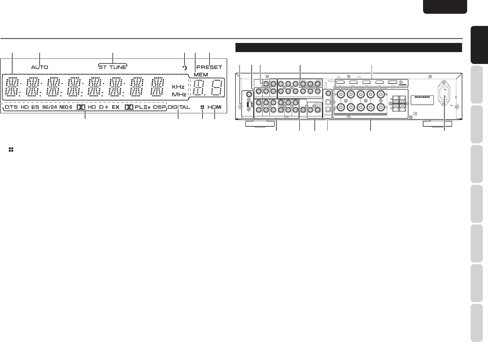
NAMES AND FUNCTIONS
¡1 SIGNAL FORMAT indicators
DTS
This indicator is illuminated when a DTS signal is
input.
DTS HD
This indicator is illuminated when a DTS-HD signal
is input.
DTS ES
This indicator is illuminated when a DTS ES signal
is input.
DTS 96/24
This indicator is illuminated when a DTS 96/24 signal
is input.
NEO:6
This indicator is illuminated when the sound is
output with the DTS Neo:6.
2 HD
This indicator is illuminated when a Dolby Digital
True HD signal is input.
2 D
This indicator is illuminated when a Dolby Digital
signal is input.
2 D +
This indicator is illuminated when a Dolby Digital
Plus signal is input.
2 D EX
This indicator is illuminated when a Dolby Digital EX
signal is input.
2 PL
IIx
This indicator is illuminated when the sound is
output with the Dolby Pro Logic IIx.
DSP
This indicator is illuminated when the sound is
output with the VIRTUAL or MULTI CH STEREO.
REAR PANEL
MODEL NO. NR1501
IN
OUT
PRE OUT
GAME
DVD
DSS
L
R
DIGITAL
AUDIO
IN
SURROUND BACK
R
L
3
2
1
GND
AM
AC IN
MODEL NO. NR1501
VIDEO
FM
(
75
Ω
)
SPEAKER SYSTEMS : 6-8 OHMS
SPEAKER SYSTEMS : 6-8 OHMS
COMPONENT VIDEO
DVD
MONITOR OUT
OUT
MONITOR OUT
IN
IN
IN
IN
IN
OUT
SUB
DVD
DSS
VCR
CD
AUX 2
WOOFER
ANTENNA
REMOTE CONTROL
ANALOG AUDIO
DSS
VCR
IN
IN
DVD
DSS
IN
VCR
P
R
/
C
R
P
R
/
C
R
P
B
/
C
B
P
B
/
C
B
Y
Y
OUT
BLU-RAY
CENTER
R
-
SURR.
-
L
R
-
FRONT
-
L
q we
yuio!0
r t
!1
q ANTENNA terminals
FM (75 Ω)
Connect an external FM antenna with a coaxial
cable, or a cable network FM source.
AM
Connect the supplied AM loop antenna. Position the
loop antenna until you hear the best reception.
w VIDEO terminals (DVD, DSS, VCR)
There are 3 video inputs and 1 video output. Connect
VCRs, DVD players, and other video components to
the video inputs.
e MONITOR OUT teminal
This is a monitor outputs.
r COMPONENT VIDEO teminals
(DVD, DSS, VCR)
This unit has 3 component video input connectors
to obtain the color information (Y, P
B/CB, PR/CR)
directly from the recorded DVD signal or other
video component and 1 component video output
connector to output it directly into the matrix
decoder of the display device.
t HDMI terminals
(BLU-RAY, GAME, DVD, DSS)
The unit has 4 HDMI inputs and 1 HDMI output.
y AC INLET
Plug the supplied power cable into this AC INLET
and then into the power outlet on the wall.
This unit can be powered by 120V AC only.
u SPEAKER SYSTEMS terminals
Seven terminals are provided for the front left,
front right, front center, surround left, surround
right, surround back left and surround back right
speakers.
i DIGITAL AUDIO IN 1, 2, 3
The unit has 1 digital input with coaxial jacks, 2 with
optical jacks.
The inputs accept digital audio signals from a CD,
DVD, or other digital source component.
The input function can be selected from the OSD
menu system. (See page 20)
o REMOTE CONTROL IN/OUT
terminals
Connect to a Marantz component equipped with
remote control (RC-5) terminals.
!0 SUB WOOFER PRE OUT terminal
Connect this jack to the line level input of a powered
subwoofer.
!1 ANALOG AUDIO terminals
(CD, DVD, DSS, VCR, AUX2)
There are 5 audio inputs and 1 audio outputs.
The audio inputs and outputs require RCA-type
connectors.
a s f h
jkl¡0
gd
k indicator
This indicator is illuminated when this unit is in the
display off mode.
l DIGITAL Indicator
This indicator is illuminated when a digital input has
been selected.


