3
NOTE: DIAGRAMS & ILLUSTRATIONS ARE NOT TO SCALE.
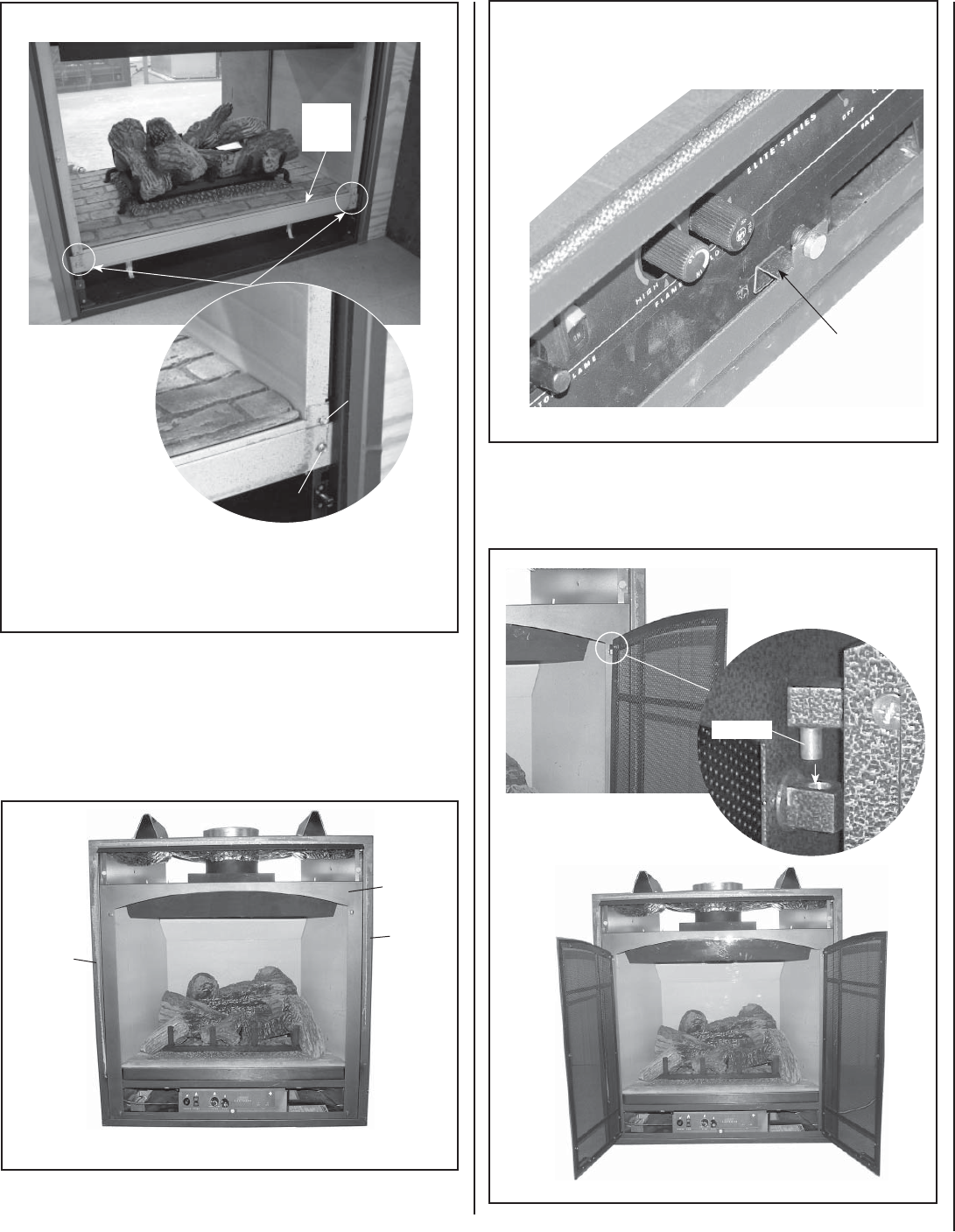
Figure 6 - INSTALL DOORFRAME
6. Place the doorframe bracket in the locked position as shown in Figure 7.
Hinge Pin
Doorframe
Bracket
Locate the doorframe
bracket on the lower front
of the doorframe and lock
it behind the cabinet
bottom fl ange as
shown here.
Figure 7
4. For EDV, EDVST & EBVST models, reinstall modesty panel, ensuring all
wires are securely connected.
5. Install Doorframe (see Figure 6) - Remove the arched doorframe
from packaging. Position the top of the doorframe above the top of the
glass doorframe (centered and approximately 1” above the top of the
glass doorframe). Slide down so that the hooks catch on the back of
the doorframe slide between the sides of the glass door and the corner
posts engaging into existing slots on fi replace.
7. Remove the screen doors from packaging. Install them by aligning
hinge pins on the doors with the hinge holes on the doorframe and
slide down (see instructions in Figure 8). Ensure the hinge pins are
fully seated onto the shoulders of the hinge holes.
Align hinge pins on the
doors with the hinge holes
on the doorframe and slide
down as shown.
Firebox
Firebox
Left
Corner
Post
Right
Corner
Post
Step 1 - Remove the
two #8 screws from
the bracket screw
cover on both sides.
Step 3 - Install the Firebox Bottom Cover Panel (#5 in Figure 1) using the
existing #10 screws. The bottom two holes on the cover panel align to cor-
responding two holes on fi rebox bottom.
Figure 5b - Install Firebox Cover
For EDVST Model Only
Step 2 - Remove the
two #10 screws from
the firebox bottom
on both sides (save
screws).
#10 Screw
#8
Screw
Adjust Doorframe Bracket
Figure 8
Bracket
Screw
Cover
Doorframe
