MAP 0120: LEDs Indicate a Fault
Diagnose a problem reported by the LEDs in the following sequence:
1. Use Table 2-2 to diagnose the error conditions reported by the system LEDs,
because these take precedence over the port LEDs. (For example, if the
system amber LED is on, it does not matter which port LEDs are on.)
Note: Throughout this manual, the term
system LEDs
refers to the green (OK)
and amber LEDs on the left side of the IBM 2210.
This table is valid after power-on or Extended POST completes.
2. If the system LEDs appear to indicate no problem, go to Step 001 in the MAP.
001
Did this LED state result from powering on the IBM 2210 normally?
Yes No
002
– Go to Step 004
003
– Go to Step 019 on page 2-6.
004
Did this LED state result from running the Extended POST?
Yes No
005
– Go to Step 007 on page 2-5.
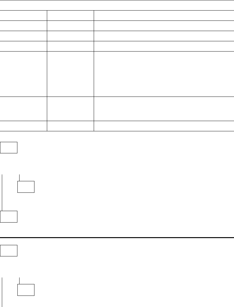
Table 2-2. System LED States
Green Amber Action
On Off Router loaded and operational.
On or Off On Replace the system board.
Off Blinking Replace the DRAM SIMM.
On Blinking There is no router load module available, no boot
configuration has been entered, or the configured
boot path is not available. Additional information can
be obtained by attaching a service terminal to the
IBM 2210. If the problem cannot be resolved locally,
call the network administrator.
Blinking On Replace the flash SIMM on models 14T and 24x.
For 12x models, refer to “MAP 0160: Service Port on
12x Model Is Not Working” on page 2-13.
Blinking Blinking Load in process.
2-4 2210 Service and Maintenance


