13-6 ColorFlex 07/02
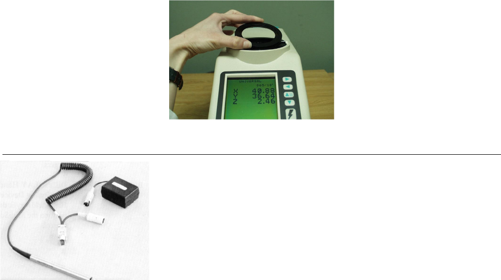
Bar Code Reader Kit
The bar code reader attaches to the communications port of the
ColorFlex and allows input of a 24-character bar code ID. An AC
adapter is also provided.
Installing the Bar Code Reader
The ColorFlex is capable of reading and storing sample IDs from a bar code reader. The bar code
reader, cable, and AC power supply may be purchased as optional equipment from HunterLab. To
assemble the bar code reader, follow the instructions below.
1. Plug the male 9-pin connector of the scanner wand into the female 9-pin connector of the short RS-
232 adapter cord. Screw the pieces together firmly.
2. Plug the opposite end of the RS-232 adapter into the right (DB-9) port on the back of the ColorFlex.
3. Power for the bar code reader is obtained from the AC power supply. Plug the round connector of
the scanner wand into the AC power supply connector.
4. Plug the AC power cord into an electrical outlet.
5. Attach the wand holder to the ColorFlex at a convenient location.
Bar Code Reader Programming
Your bar code reader will come pre-programmed by HunterLab. However, if unforeseen circumstances
require that you re-program it, follow the instructions below.
The bar code reader must have three firmware features modified from the factory default in order to
work with the ColorFlex sensor. These changes are made by reading the available bar codes in the
Programming Menu. Use the following sequence to set the features for use with the ColorFlex sensor.
All three features to be changed are located on the “Input/Output Parameters & Format” pages (pp. 4
and 5) of the Programming Menu. This command sequence uses the ENTER and EXIT codes found on
the Input/Output pages and the scan codes found on the inside of the back cover. Unfold the back cover
so that you can access all three pages at once.


