168-082010_ 210-212 Meter/Controller Page 8 of 17
The standard inlet and outlet fittings for the 210/212 are 0.25” and 0.125” Swagelok (optional VCR or VCO
fittings). The O-rings for the end cap and the sensor are Viton (optional Kalrez or Neoprene). It is suggested
that all connections be checked for leaks after installation. This can be done by pressurizing the instrument
(do not exceed 500 psig unless the Flowmeter is specifically rated for higher pressures) and applying a diluted
soap solution to the flow connections rated for higher pressures) and applying a diluted soap solution to the
flow connections.
2.5. Electrical Connections
If a power supply from Hastings Instruments is used, installation consists of connecting the HFM-210/HFC-
212 series cable from the “D” connector on the rear of the power supply to the “D” connector on the top of
the Flowmeter. If a different power supply is used, follow the instructions below when connecting the flow
meter.
This HFM-210/HFC-212 series requires Hastings cable #AF-8AM. Use of any other cable can severely
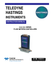
damage the instrument and void the warranty. Figure 2.1 shows the schematic layout for connecting the
instrument to an appropriate power supply.
The power supply used must be capable of supplying +15VDC at 50mA and -15VDC at -200mA for each
controller. These voltages must be referenced to a common ground. Connect -15VDC to pin 9 and +15VDC
to pin 11. Pins 5 and 12 are both commons and they must be connected together and to the ground
connection at the power supply. Do not connect them together at the flow controller as the resulting crosstalk
could result in flow instabilities. Pin 7 is the case ground. It should be connected to the cable shield if
available and to the AC ground to the power supply.
Pin 6 is the output signal from the flow controller. This output will be 0-5VDC, 5VDC being 100% of rated or
full flow. Pin 14 is the command input. This should be a 0-5VDC signal and must be free of spikes or other
electrical noise, as these will generate false flow commands that the controller would attempt to flow. Pin 15 is
a well regulated +5.00VDC output reference. The reference is designed to provide the command signal for pin
14 by connecting one end of a potentiometer to pin 15 and the other end to ground. The center lead would
then be connected to pin 14.
If a valve override switch is not desired, the unit is ready for use at this time. If the override switch is desired,
connect the center pin of a single pole, three-position switch with the center off position to pin 8. Connect
+15VDC to one end of the switch, and -15VDC to the other end. This will result in the valve being full open
when +15VDC is supplied to pin 8, off when -15VDC is supplied and auto-control when there is no
connection to pin 8 (OPEN-AUTO-CLOSE). This setup will be adequate for most purposes, but there will be
a small delay for capacitors to
charge between switch operation
and control override.
2.6. Operation
The standard instrument output
is a 0 - 5 VDC out and the signal
is proportional to the flow i.e., 0
volts = zero flow and 5 volts =
100% of rated flow. The 4 - 20
mA option is also proportional to
flow, 4 mA = zero flow and 20
mA = 100% of rated flow. It is
suggested that all connections be
checked for leaks after installation.
This can be done by pressurizing
the instrument (do not exceed
500 psig unless the instrument is
specifically rated for higher
pressures) and applying a diluted
soap solution to the connections.
Fig 2.1