SW6 VGA Audio • Installation and Operation
Installation and Operartion, cont’d
2-4
SW6 VGA Audio • Installation and Operation
2-5
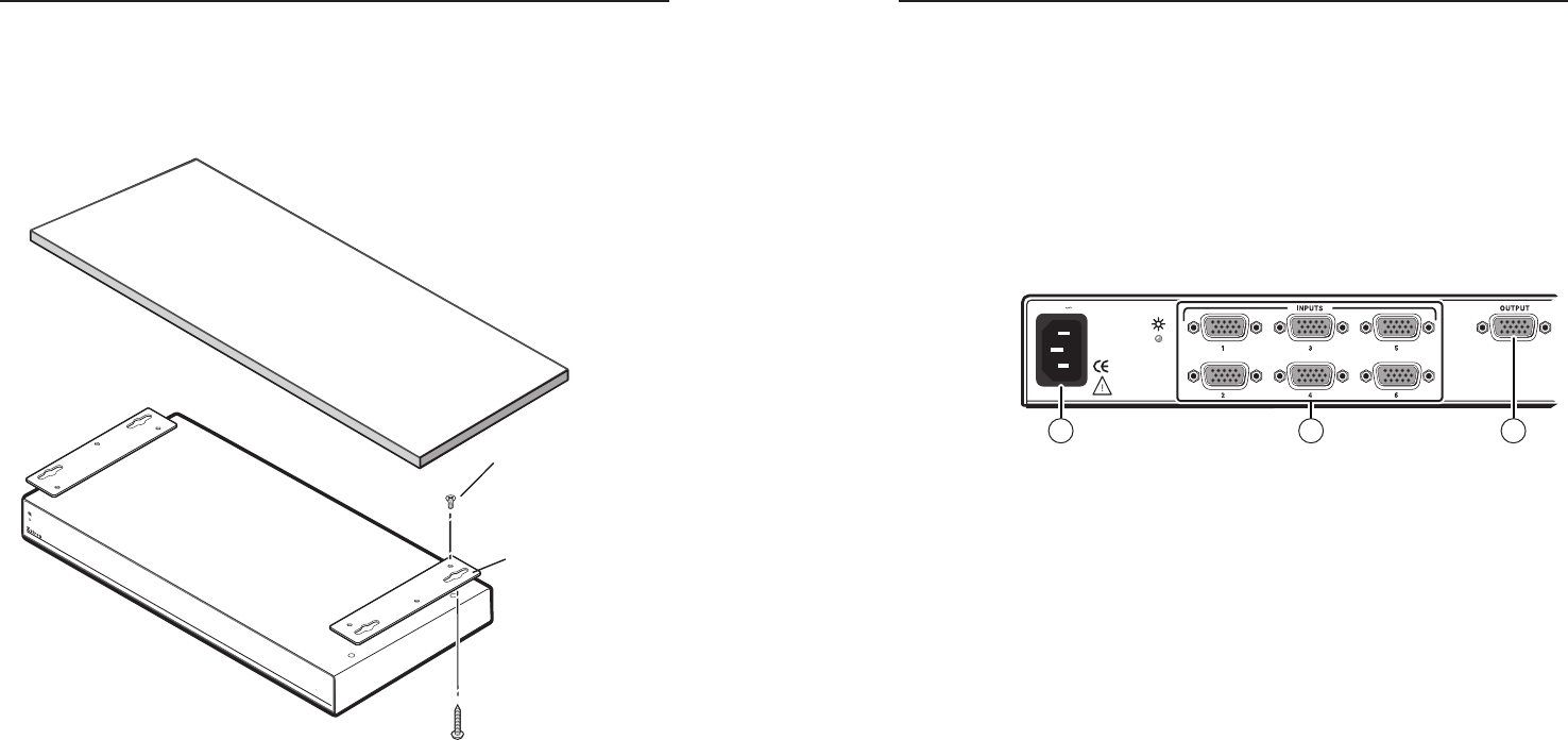
Under furniture mounting
If desired, mount the SW6 VGA Audio under a desk or other
furniture (figure 2-2) with the optional MBU 129 under-desk
mounting bracket (part #70-219-01), as follows:
SW6 V
GA A
UDIO
Under Desk
Mounting Bracket
(4) Screws
Remove and discard
(4) screws from top.
Replace with supplied
screws.
Figure 2-2 — Mounting the unit under a desk
1. If installed, remove the feet from the bottom of the unit.
2. Remove and discard the four screws in the top of the
switcher.
3. Using the screws supplied in the mounting bracket kit,
secure the mounting brackets to the top of the switcher
with the slotted holes on the outside.
4. Hold the switcher with the attached brackets against the
underside of the table or other furniture. Mark the location
of the brackets’ slotted screw holes on the mounting
surface.
5. Drill 3/32" (2 mm) diameter pilot holes, 1/4" (6.3 mm)
deep in the mounting surface at the marked screw
locations.
6
. Insert #8 wood screws into the four pilot holes. Tighten
each screw into the mounting surface until just less than
1/4” of the screw protrudes.
7. Align the mounting screws with the slots in the brackets
and place the switcher against the surface, with the screws
through the bracket slots.
8. Slide the switcher slightly forward or back, then tighten all
four screws to secure the switcher in place.
Connections
50/60 Hz
100-240V 0.3A
31 2
Figure 2-3 — SW6 VGA A rear panel (left half)
a
AC power connector — Plug a standard IEC power cord
into this connector to connect the switcher to a 100 VAC to
240 VAC, 50 or 60 Hz power source.
b
Video Input connectors — Connect up to six RGBHV computer
video (VGA–QXGA) to these 15-pin HD connectors.
N
The switcher can also accept RGBS, RGsB, RsGsBs, and
HDTV component video.
c
Video Output connector — Connect an RGBHV (VGA-QXGA)
video display to this female 15-pin HD connector.


