2-18
PoleVault Systems Installation • Installation — Stage 3
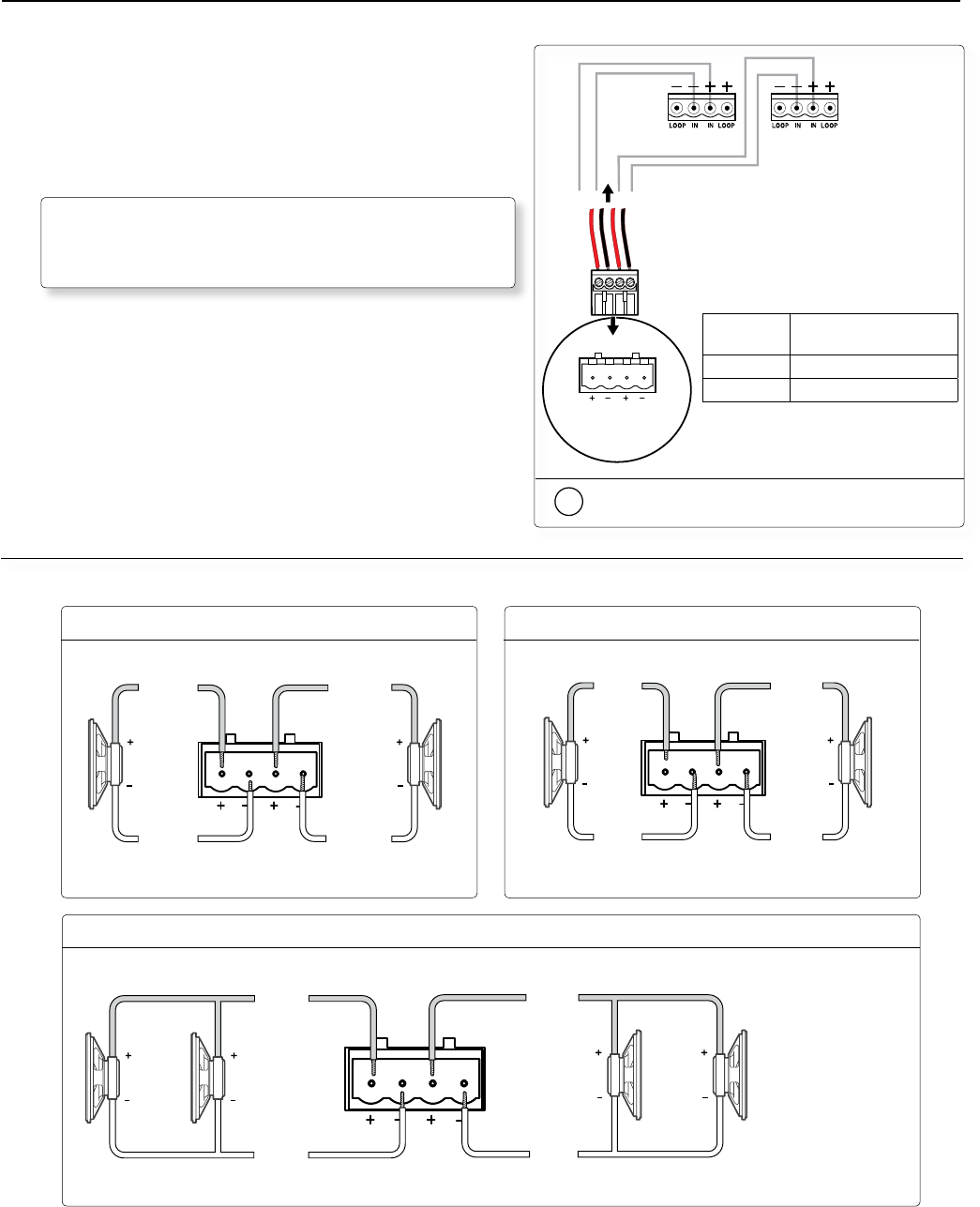
Wire the captive screw connector.
PVS Switcher
Rear Panel
Speaker 1 Speaker 2
LR
4/8
Ohms
AMPLIFIED OUTPUTS
4-pole Captive
Screw Connector
Audio output
to speakers
8 Ohm Load
Stereo R–
Stereo R+
Stereo L–
LR
8 Ohms
AMPLIFIED OUTPUTS
Stereo L+
Stereo or dual mono output using parallel speaker wiring
Stereo output
Dual mono output
8 Ohm Load
LR
8 Ohms
AMPLIFIED OUTPUTS
Mono –
Mono +
Mono –
Mono +
4 Ohm Total Load4 Ohm Total Load
Two 8 ohm speakers
wired in parallel
equal a 4 ohm load.
LR
4/8 Ohms
AMPLIFIED OUTPUTS
Mono –
or
Stereo R-
8
ohms
8
ohms
Mono +
or
Stereo R+
Mono –
or
Stereo L-
Mono +
or
Stereo L+
8
ohms
8
ohms
Speaker
Wire color
To PVS 305SA terminal
(Left and Right)
Red Positive (+)
Black Negative (-)
3. Terminate the speaker cable for the PVS
switcher
a. To terminate the cable, strip the end of the cable 0.2 inch
(5 mm) and secure the wires into the supplied
4-pole captive screw connector.
N
The correct speaker impedance loading must be
observed when setting up a speaker system.
See figures below for examples.
N
By default, the amplifier is set for dual mono output. Use the software or SIS
™
(Extron Special Instruction Set)
commands to change the setting to stereo if desired. For full details, refer to the PVS 305SA Users Manual,
available online at www.extron.com


