5900335 © 2005 JCM-American Corporation
3-4
Section 3 Optipay™ CC DESIGN
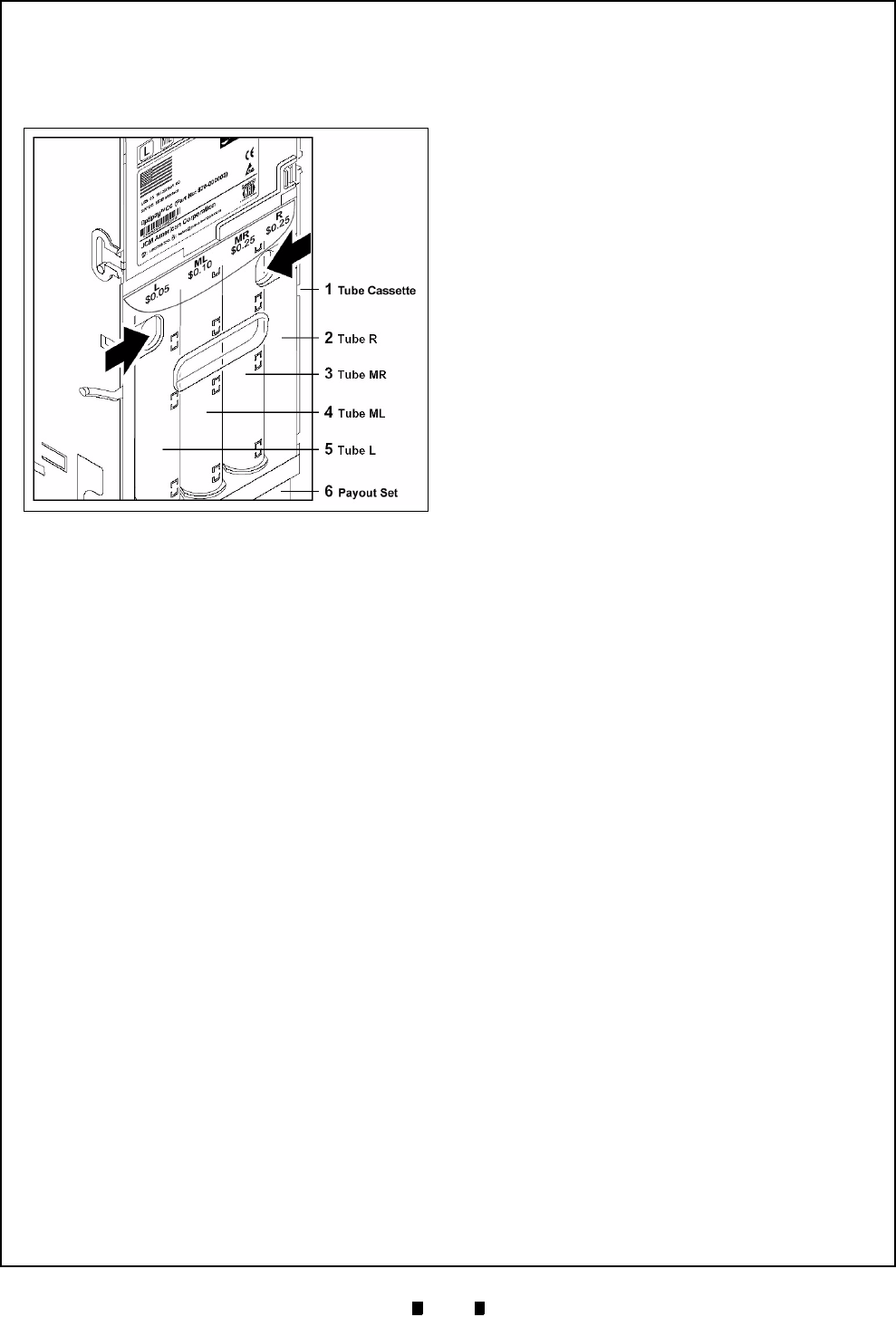
If at any time another combination of tube coins is
required, the appropriate cassette can be ordered
from the JCM and simply exchanged in the
assembly (See Figure 3-6 [1]).
Payout Module
Vending change is done by two motors installed at
the bottom of the Payout Set (See Figure 3-1 [6]),
which rotate in order to vend the desired coins.
The left side motor is responsible for vending the
left “
Tube L
(5)” and middle left “
Tube ML
(4)”
tube coins, and the right side motor is responsible
for vending the right “
Tube R
(2)” and middle right
“
Tube MR
(3)” tube coins.
Filling Level Sensors
The capacity of each tube is monitored by four
independent sensors viewing the number of it’s
related coins:
•
An empty sensor is positioned at the height of
8 to 10 collected coins
•
A 50% sensor approximately half way up
•
A 75% sensor near the top, and
•
A full sensor is positioned at the top rim of
each tube.
In order for the tube counters to function without
fault when the change tubes are filled by inserting
coins through the Coin Changer, or when the tubes
are filled by removing the four Tube Cassette, the
filling level sensors must check the tube counter’s
status after every coin acceptance and coin vend.
If the number of coins does not correspond with the
measured tube capacity level, the tube count will
be corrected depending on the respective tubes
coin thickness.
If a tubes "full" sensor displays the message "tube
full", all further coins for this tube will be auto-
matically directed to the Cash Box. Only when
coins have been vended again from this tube, will
more coins be allowed into the tube.
MDB Vending Machine Cable
The MDB Interface Connecting Cable (See Figure
3-1 [10]) to the Vending Machine is installed at
the top left corner of Coin Changer. For details of
how to install the Coin Changer into a Vending
Machine, see section 5 "Installation".
Figure 3-6 Tube Cassette Removal/Replacement


