4
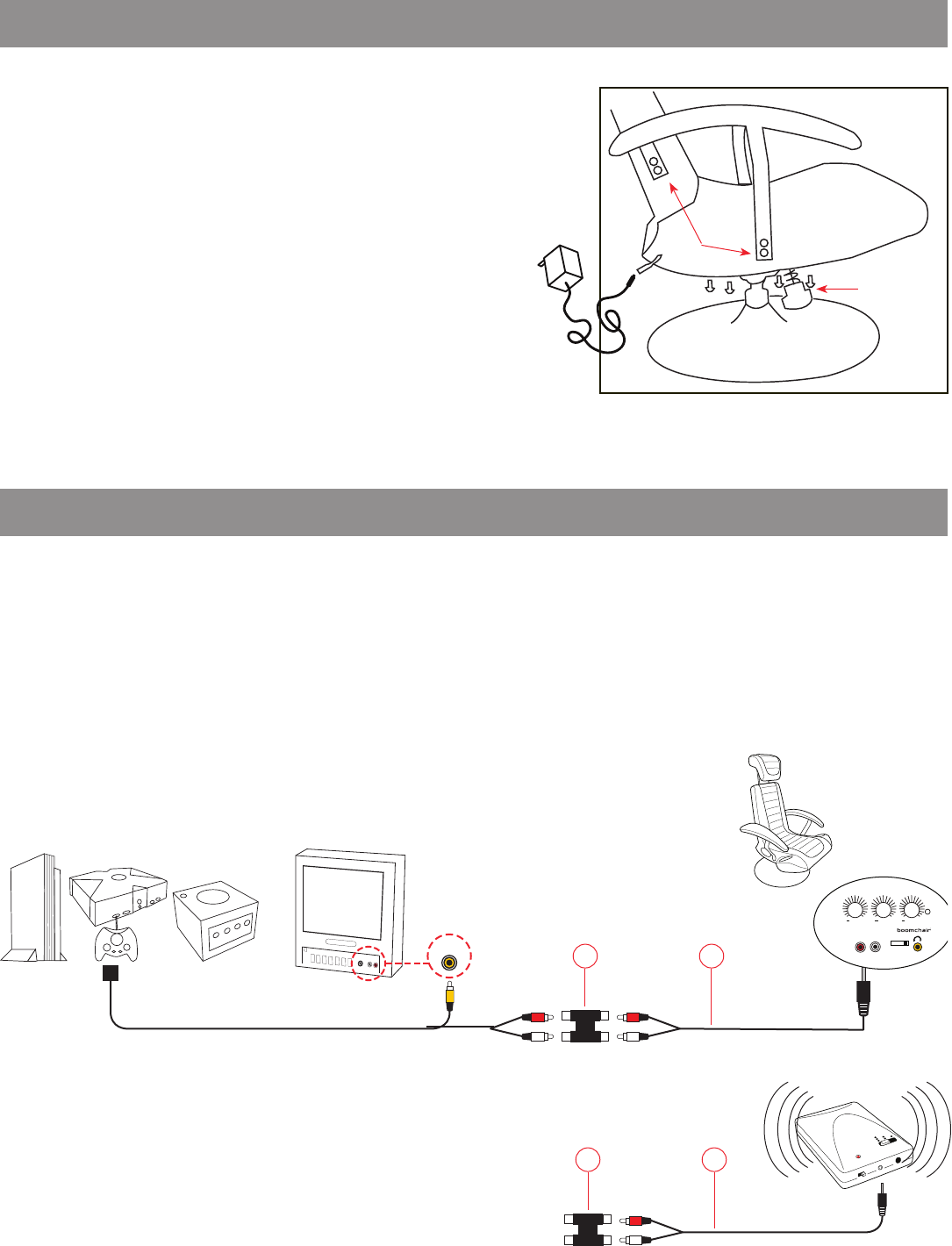
Step 1: Using the console’s custom RCA cord, plug yellow
composite video cable from game console into video input of TV. (Fig. 1)
Step 1: Connect Audio Coupler (3b) to Red/White RCA cord from game console.
Step 2: Connect one end of RCA cord (3b) into other end of Audio Coupler (3b).
Step 3: Connect single end of audio cord (3a) into INPUT of BoomChair®.
Note: Most game consoles are supplied with a custom connector with yellow video out and RCA red/white audio out.
INPUT OUTPUT
0 3 2 1
POWER
VIBRATION
+
BASS/TREBLE
+
VOLUME
+
IN
3b
3a
GAME CONSOLE TV BOOMCHAIR™
Fig. 1
Fig. 2
Cable supplied with game console
Fig. 3
AUDIO COUPLER (3c)
ASSEMBLY INSTRUCTIONS
Step 1: Secure the SWIVEL/TILT KNOB UNIT to the bottom of chair
using 4 screws and the provided allen wrench. Make sure knob is on
the front side of the chair as pictured.
Step 2: Insert the pole portion into the metal base and apply pressure
or carefully sit in chair to lock in place.
Step 3: Make sure chair is in upright position and secure the hook and
loop fasters on back of chair (part 5)
Step 4: Use allen wrench to attach armrests using 4 screws each.
Step 5: Insert headrest by squeezing button on top of back.
Step 6: Insert adapter cord (2) into power receptacle (4).
Step 7: Plug adapter (2) into wall outlet.*
Step 8: Turn Boomchair™ on by turning Power knob (C) clockwise.
STEP 1
STEP 6
*CAUTION: Use only provided adaptor! Different voltage may cause permanent damage.
CONNECTING TO GAME CONSOLES
STEP 4
3b
3a
Step 1: Connect Audio Coupler (3b) to Red/White RCA cord from game
console.
Step 2: Connect red/white end of RCA cord (3a) into other end of Audio
Coupler (3b). (Fig. 4)
Step 3: Connect mini audio end of RCA cord (3a) into Wireless
Transmitter. (Fig. 5)
Step 3: Set transmitter and channel switch (F) to matching frequency.
WIRELESS CONNECTION
Fig. 4
Fig. 5
DIRECT CONNECTION - BE SURE THE WIRELESS CHANNEL SELECTOR IS SWITCHED TO “0”


