Quick Reference 1
Series N6700 User’s Guide 11
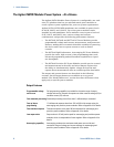
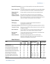
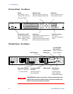
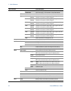
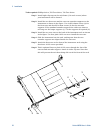
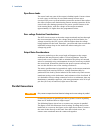
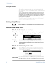
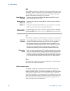
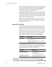
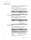
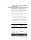
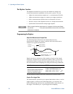
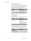
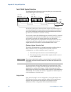
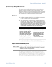
Front Panel Display – At a Glance
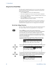
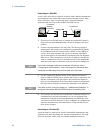
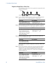
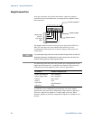
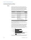
Single-channel view Voltage
measurement
Bar indicates output
polarity is reversed
Current
measurement
Press the Meter key
to toggle between
views
Operating status
(CV = constant voltage)
Voltage and
current settings
Interface status
(IO
= activity on interface)
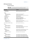
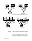
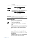
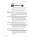
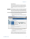
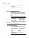
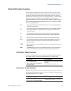
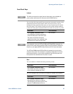
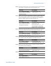
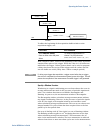
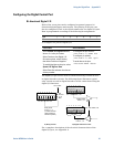
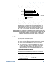
Multiple-channel view Voltage and Current measurements
Press the Meter key
to toggle between
views
The highlighted channel is the active channel
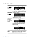
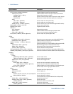
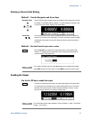
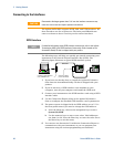
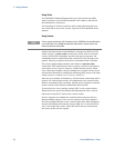
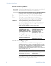
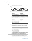
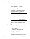
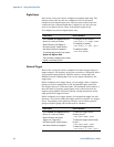
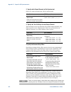
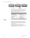
Grouped-channel view Channels 2 through 4 are connected in parallel and have been
configured or grouped to act as a single, higher-power channel
Refer to Chapter 4,
under “System-Related
Operations” for more
information
Grouped channels are addressed using the channel number of the
lowest channel in the group
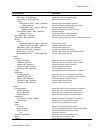
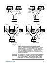
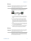
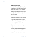
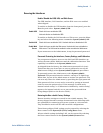
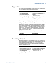
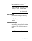
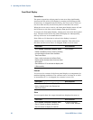
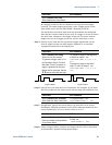
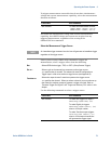
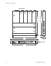
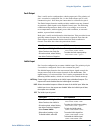
Double-wide view Channel 2 is a double-wide power module that occupies two channel
locations in the mainframe
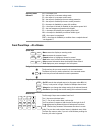
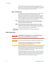
Interface status
indicators
All = the On/Off key is active on all channels
Err = an error has occurred (press Error key to display error message)
Lan = the LAN is connected and has been configured
IO = there is
activity on one of the remote interfaces