TRACER 5045 System Manual Section 3 Engineering Guidelines
612805045L1-1A © 2003 ADTRAN, Inc. 27
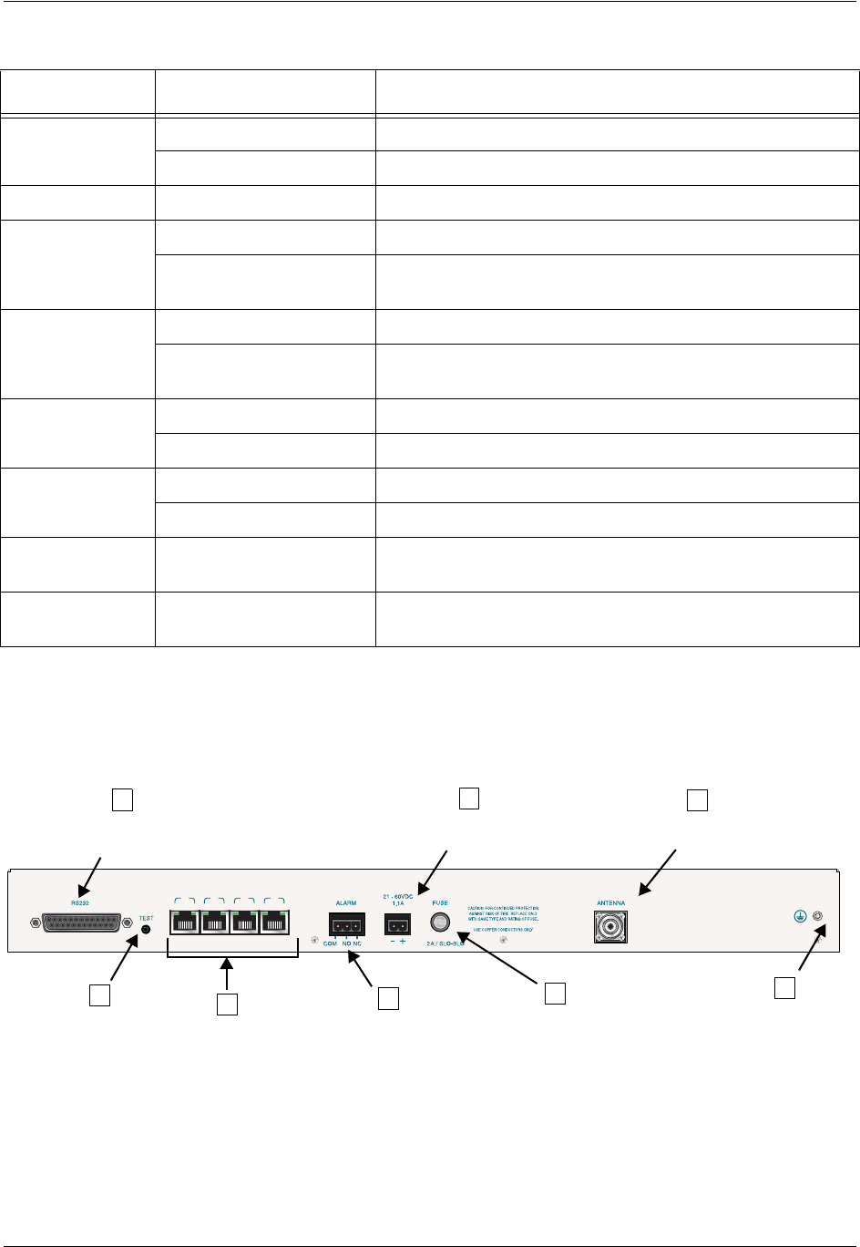
4. REVIEWING THE TRACER 5045 REAR PANEL DESIGN
Figure 2 identifies the various features of the TRACER 5045 rear panel and Table 1 on page 26 provides a
brief description of each interface.
Figure 2. TRACER 5045 Rear Panel
Table 2. TRACER 5045 LEDs
For these LEDs... This color light... Indicates that...
PWR
Green (solid) the TRACER 5045 is connected to a power source.
Off the TRACER 5045 is not currently powered up.
TST Amber (solid) there is an active test being performed by the system.
LAN (1–4)
Green there is a valid 10/100BaseT/TX link.
Amber (blinks with activity)
there is data activity (transmit or receive data) on the
10/100BaseT/TX LAN interface.
WAN
Green there is a valid wireless link.
Amber (blinks with activity)
there is data activity (transmit or receive data) over the wireless
link.
PLAN A
Green (solid) the TRACER 5045 is transmitting on Frequency Plan A.
Off the TRACER 5045 is not transmitting on Frequency Plan A.
PLAN B
Green (solid) the TRACER 5045 is transmitting on Frequency Plan B.
Off the TRACER 5045 is not transmitting on Frequency Plan B.
RF LOW Red (solid)
the RSSI level is below suggested minimum threshold
(approximately 10 dBm above the minimum receive sensitivity).
RF DOWN Red (solid)
there is a communication problem between the local and remote
TRACER 5045 systems.
LNK ACTLNK ACTLNK ACTLNK ACT
12
10/100 BASE - T/ TX
34
A
Antenna
DC Power
Connection
Connector
RS232
Interface
(VT100 Terminal)
Ground
Lug
Fuse
Alarm
Contacts
Test
E
G
B
C
D
F
H
Ethernet
Interfaces


