


2
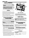
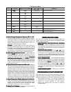
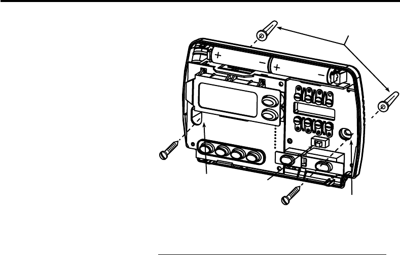
Mounting
holes
Mounting
holes
Electric/Gas
switch
Screw anchors
INSTALLATIONINSTALLATION
INSTALLATIONINSTALLATION
INSTALLATION
REMOVE OLD THERMOSTATREMOVE OLD THERMOSTAT
REMOVE OLD THERMOSTATREMOVE OLD THERMOSTAT
REMOVE OLD THERMOSTAT
1. Shut off electricity at the main fuse box until installation is
complete. Ensure that electrical power is disconnected.
2. Remove the front cover of the old thermostat.
With wiresWith wires
With wiresWith wires
With wires
still attached, still attached,
still attached, still attached,
still attached, remove wall plate from the wall. If the old
thermostat has a wall mounting plate, remove the thermo-
stat and the wall mounting plate as an assembly.
3.
Identify each wire attached to the old thermostat usingIdentify each wire attached to the old thermostat using
Identify each wire attached to the old thermostat usingIdentify each wire attached to the old thermostat using
Identify each wire attached to the old thermostat using
the labels enclosed with the new thermostat.the labels enclosed with the new thermostat.
the labels enclosed with the new thermostat.the labels enclosed with the new thermostat.
the labels enclosed with the new thermostat.
4. Disconnect the wires from old thermostat one at a time.
DODO
DODO
DO
NOT LET WIRES FALL BACK INTO THE WALL.NOT LET WIRES FALL BACK INTO THE WALL.
NOT LET WIRES FALL BACK INTO THE WALL.NOT LET WIRES FALL BACK INTO THE WALL.
NOT LET WIRES FALL BACK INTO THE WALL.
5. Install new thermostat using the following procedures.
ATTENTION!ATTENTION!
ATTENTION!ATTENTION!
ATTENTION!
This product does not contain mercury. However, this product
may replace a unit which contains mercury.
Do not open mercury cells. If a cell becomes damaged, do not
touch any spilled mercury. Wearing nonabsorbent gloves, take
up the spilled mercury with sand or other absorbent material and
place into a container which can be sealed. If a cell becomes
damaged, the unit should be discarded.
Mercury must not be discarded in household trash. When the
unit this product is replacing is to be discarded, place in a
suitable container and return to White-Rodgers at 2895 Harrison
Street, Batesville, AR 72501 for proper disposal.
ELECTRIC HEAT OR SINGLE-STAGEELECTRIC HEAT OR SINGLE-STAGE
ELECTRIC HEAT OR SINGLE-STAGEELECTRIC HEAT OR SINGLE-STAGE
ELECTRIC HEAT OR SINGLE-STAGE
HEAT PUMP SYSTEMSHEAT PUMP SYSTEMS
HEAT PUMP SYSTEMSHEAT PUMP SYSTEMS
HEAT PUMP SYSTEMS
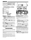
This thermostat is configured from the factory to operate a heat/
cool, fossil fuel (gas, oil, etc.), forced air system. It is configured
correctly for any system that DOES NOT require the thermostat
to energize the fan on a call for heat. If your system is an electric
heat or heat-pump system that REQUIRES the thermostat to
turn on the fan on a call for heat, locate the
GAS/ELECTRICGAS/ELECTRIC
GAS/ELECTRICGAS/ELECTRIC
GAS/ELECTRIC
switch switch
switch switch
switch on the back of the thermostat (see fig. 1) and switch it to
the
ELECTRIC ELECTRIC
ELECTRIC ELECTRIC
ELECTRIC position. This will allow the thermostat to ener-
gize the fan immediately on a call for heat. If you are unsure if
the heating/cooling system requires the thermostat to control
the fan, contact a qualified heating and air conditioning service
person.
ATTACH THERMOSTAT BASE TO WALLATTACH THERMOSTAT BASE TO WALL
ATTACH THERMOSTAT BASE TO WALLATTACH THERMOSTAT BASE TO WALL
ATTACH THERMOSTAT BASE TO WALL
1. Remove the packing material from the thermostat. Gently
pull the cover straight off the base. Forcing or prying on the
thermostat will cause damage to the unit. If necessary, move
the electric heat switch (see
ELECTRIC HEAT SYSTEMSELECTRIC HEAT SYSTEMS
ELECTRIC HEAT SYSTEMSELECTRIC HEAT SYSTEMS
ELECTRIC HEAT SYSTEMS,
above).
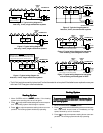
2. Connect wires beneath terminal screws on base using
appropriate wiring schematic (see figs. 2 through 7).
3. Place base over hole in wall and mark mounting hole
locations on wall using base as a template.
4. Move base out of the way. Drill mounting holes.
5. Fasten base loosely to wall, as shown in fig. 1, using two
mounting screws. Place a level against bottom of base,
adjust until level, and then tighten screws. (Leveling is for
appearance only and will not affect thermostat operation.) If
you are using existing mounting holes, or if holes drilled are
too large and do not allow you to tighten base snugly, use
plastic screw anchors to secure subbase.
6. Push excess wire into wall and plug hole with a fire-resistant
material (such as fiberglass insulation) to prevent drafts
from affecting thermostat operation.
BATTERY LOCATIONBATTERY LOCATION
BATTERY LOCATIONBATTERY LOCATION
BATTERY LOCATION
2 "AA" alkaline batteries are included in the thermostat at the
factory with a battery tag to prevent power drainage.
You mustYou must
You mustYou must
You must
remove the battery tag to engage the batteriesremove the battery tag to engage the batteries
remove the battery tag to engage the batteriesremove the battery tag to engage the batteries
remove the battery tag to engage the batteries.
If
“BATT”“BATT”
“BATT”“BATT”
“BATT” is displayed, the batteries are low and should be
replaced with fresh "AA" Energizer
®
alkaline batteries. To
replace batteries, install the batteries along the top of the base
(see Fig. 1). The batteries must be installed with the positive (+)
end to the left.
HYDRONIC (HOT WATER OR STEAM)HYDRONIC (HOT WATER OR STEAM)
HYDRONIC (HOT WATER OR STEAM)HYDRONIC (HOT WATER OR STEAM)
HYDRONIC (HOT WATER OR STEAM)
HEATING SYSTEMSHEATING SYSTEMS
HEATING SYSTEMSHEATING SYSTEMS
HEATING SYSTEMS
This thermostat is set to operate properly with a forced-air
heating system. If you have a hydronic heating system (a
system that heats with hot water or steam), you must set the
thermostat to operate properly with your system. Change the
second option in the configuration menu to SL (see CONFIGU-
RATION MENU, page 4).
CHECK THERMOSTAT OPERATIONCHECK THERMOSTAT OPERATION
CHECK THERMOSTAT OPERATIONCHECK THERMOSTAT OPERATION
CHECK THERMOSTAT OPERATION
If at any time during testing your system does not operate
properly, contact a qualified service person.
Turn on power to the system.
Fan OperationFan Operation
Fan OperationFan Operation
Fan Operation
If your system
does notdoes not
does notdoes not
does not have a
GG
GG
G terminal connection, skip to
Heating SystemHeating System
Heating SystemHeating System
Heating System.
1. Move FAN switch to ON position. The blower should begin
to operate.
2. Move FAN switch to
AUTO AUTO
AUTO AUTO
AUTO position. The blower should
stop immediately.
Figure 1. Thermostat BaseFigure 1. Thermostat Base
Figure 1. Thermostat BaseFigure 1. Thermostat Base
Figure 1. Thermostat Base