


www.ti.com
1.3EVMBasicFunctions
Overview
CAUTION
WhenapplyinganexternalvoltagereferencethroughTP2orJ4-20,makesure
thatitdoesnotexceed+5Vmaximum.Externalvoltagereferencesinexcessof
+5VcanpermanentlydamagetheDAC8555beingtested(U1).
TheDAC8555EVMisdesignedtoprovideademonstrationplatformfortestingcertainoperational
characteristicsoftheDAC8555digital-to-analogconverter.FunctionalevaluationoftheDAC8555canbe
accomplishedwiththeuseofanymicroprocessor,TIDSPorsomesortofwaveformgenerator.
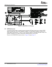
HeadersJ2A(topside)andJ2B(bottomside)arepass-throughconnectorsprovidedtointerfaceahost
processororwaveformgeneratorwiththeDAC8555EVMusingacustom-builtcable.Theseconnectors
enablethecontrolsignalsanddatatopassbetweenthehostandthedevice.
Amatingadapterinterfacecard(5-6kadapterinterface)isalsoavailabletofitwithTI’sTMS320C5000™
andTMS320C6000™DSPStarterKits(DSKs).Thiscardresolvesmostofthetroubleinvolvedwith
buildingacustomcable.Additionally,thereisalsoanMSP430-basedplatform(HPA449)thatusesthe
MSP430F449microprocessor,towhichthisEVMcanconnectandinterfaceaswell.Formoredetailsor
informationregardingthe5-6kadapterinterfacecardortheHPA449platform,pleasecontactyourTexas
Instrumentsrepresentative,visittheTIwebsiteoremailtheDataConverterApplicationsSupportTeamat
dataconvapps@list.ti.com.
TheDACoutputscanbemonitoredthroughtheselectedpinsoftheJ4headerconnector.Alloutputscan
beswitchedthroughtheirrespectivejumpers—JMP11,JMP12,JMP13andJMP14—forthepurposeof
stacking.StackingallowsatotalofeightDACchannelstobeused,providedtheSYNCsignalsareunique
foreachEVMboardstacked.
Inaddition,theoptionofselectingoneDACoutputthatcanbefedtothenoninvertingsideoftheoutput
opamp,U2,isalsopossiblebyusingajumperacrosstheselectedpinsofJ4.Theoutputopamp(U2)
mustfirstbecorrectlyconfiguredforthedesiredwaveformcharacteristic.Formoreinformation,referto
Section3ofthisuser’sguide.
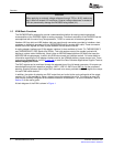
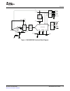
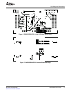
AblockdiagramoftheEVMisshowninFigure1.
4DAC8555EVMUser'sGuideSLAU204–December2006
SubmitDocumentationFeedback