Model 9060L
Teledyne Analytical Instruments viii
List of Figures
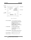
Figure 1-1: Front Panel ................................................................ 12
Figure 1-2 Rear Panel................................................................... 14
Figure 2-1: Model 9060L Oxygen Probe ....................................... 16
Figure 2-2: Model 9060L Probe..................................................... 17
Figure 2-3: Internal Structure of the Zirconia Sensor and Probe... 18
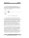
Figure 2-3: Signal Processing Block Diagram............................... 21
Figure 3-1: Oxygen Probe Mounting ............................................. 25
Figure 3-2: Model 9060L Rear panel............................................. 26
Figure 3-3: Contact ID for FAILSAFE Relay Operation ................. 27
Figure 3-4:Model 9060L Heated Probe Cable Connection............ 28
Figure 3-5: Connections to Probe ................................................. 29
Figure 4-1: Front Panel Controls and Indicators............................ 31
Figure 4-2: Calibration Port on Probe Head .................................. 35
Figure 5-1: AC Fuse Replacement................................................ 41


