


Trace Oxygen Analyzer Installation
Teledyne Analytical Instruments 11
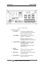
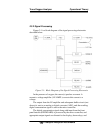
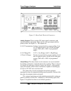
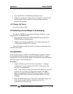
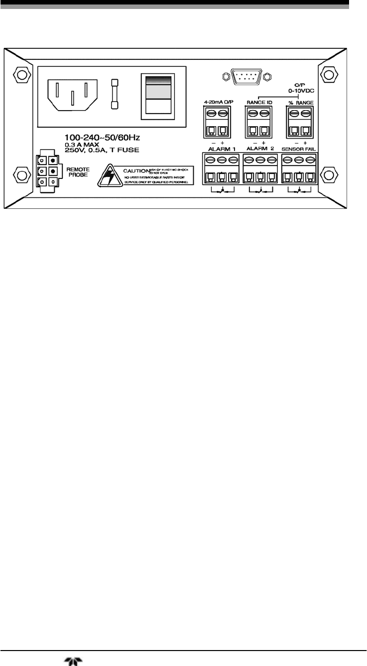
Figure 3-1: Rear Panel Electrical Connectors
Analog Outputs: There are three DC output signal connectors with
screw terminals on the panel. There are two wires per output with the
polarity noted. See Figure 3-1. The outputs are:
0–10 V Concentration: Voltage is proportional to oxygen reading, from
0 V at 0 ppm oxygen to 10 V at full scale ppm
oxygen. (Full scale = 100% of programmed
range).
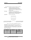
0–10 V Range ID: 3.33 V = Low Range, 6.66 V = High Range
4–20 mA % Range: Current is proportional to oxygen reading, from 4
mA at 0 ppm oxygen to 20 mA at full scale ppm
oxygen. (Full scale = 100% of programmed
range).
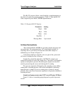
Alarm Relays: The three alarm circuit connectors are screw terminals
for making connections to internal alarm relay contacts. There is one set
of contacts for each type of alarm. Contacts are Form C, with normally
open and normally closed contact connections capable of switching up
to 0.5A at 125 VAC into a resistive load.
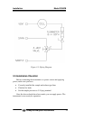
The alarm relay circuits are designed for failsafe operation,
meaning the relays are energized during normal operation. If power fails
the relays de-energize (alarms activated).
The contact connections are indicated diagrammatically on the rear
panel as normally closed (NC), common (C), and normally open (NO).
Figure 3-2 explains how these act in failsafe operation.